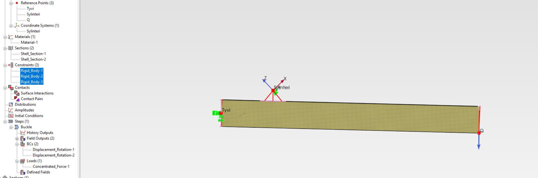
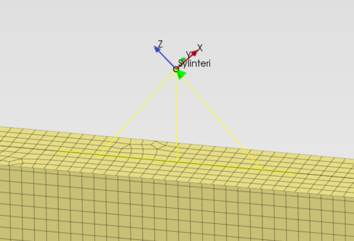
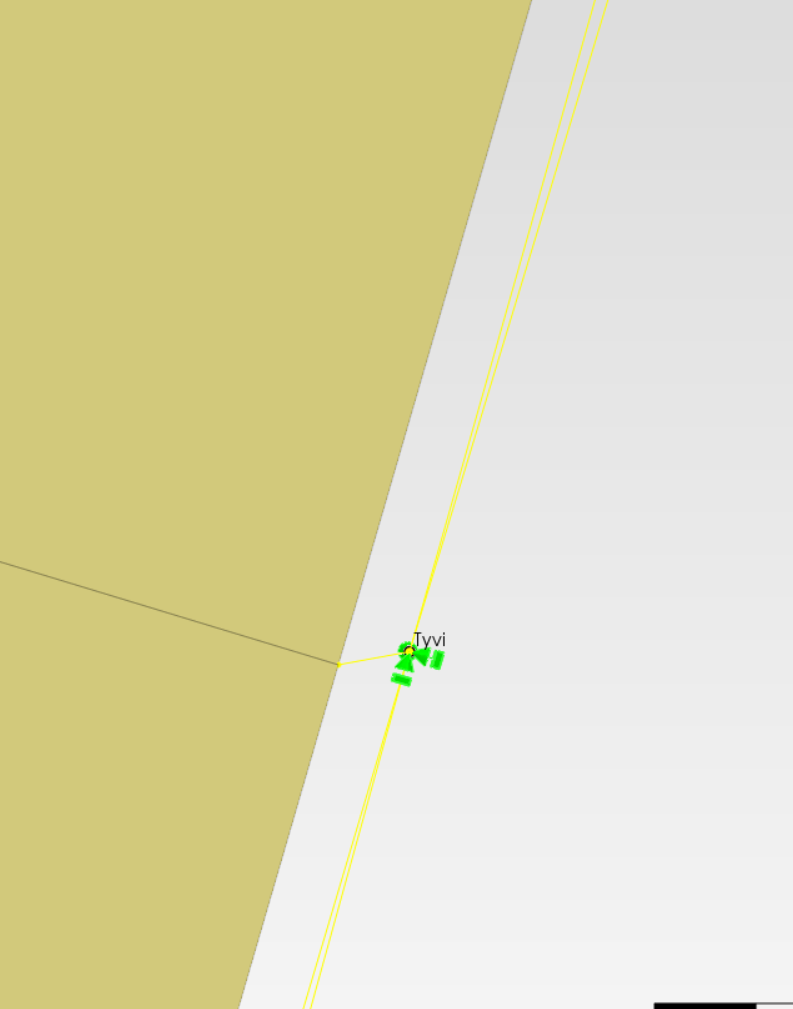
I’m working on a shell I-beam buckling analysis. I’m having trouble making heads or tails of this. I suspect the issue may be with with the rigid bodies I’m trying to set up. I want the beam face at the support end to act as a pinned joint about the Y-axis, the support at 1 meters is rotated 45° and fixed only in the local coordinate system’s Z-axis. This is supported with a rigid link to a 500 mm edge at the middle of the top flange. The reference points near existing nodes are offset by ≈ 1 mm so there should be no interferance.
The point load Q is to be placed at the free end at the tip of the bottom flange. I can’t seem to be able to get a sensible result from the buckling analysis. I was excited because I initial input the critical moment and got a buckling factor of ≈ 0,97. However, I get the same kind of result regardless of the point load at the end.
There are known CalculiX issues with shells too (due to their internal expansion to solids). It’s often better to try with solid elements when encountering problems like that. In PrePoMax, it’s really easy since you can use the Thicken Shell Mesh tool to quickly create a solid mesh from your shell mesh. Some analysis features have to be redefined though.
It’s good practice to first run a frequency analysis to check there are no rigid body modes or disconnected parts that will mess the Buckling analysis.
Additionally, I have experienced some Buckling analisys problems with shells and offsets in the past. I would try if removing offsets solves the problem. If yes, then I would go to solid elements as workarround if you need that extra accuracy.
Currently it’s tied to the edge of the web for a span of 500 mm. When I change it to the flange edge or the whole web area below, the buckling factors become more realistic. I think I’ll model a shell lug for the cylinder support to see if that helps.
Also the rigid links at the ends - they appear unsymmetrical but is that just a graphical representation issue?
I tried removing rigid body constraints from your model and applied BCs and loads to single nodes (create node sets), and the model works as expected. I think rigid body connections are to blame.
Maybe add additional shell elements with a large thickness instead of a rigid connection. Or try adding kinematic or distributing coupling by keywords.
Yes, this way you don’t have to multiply the buckling factor by the applied load. And you avoid the aforementioned ccx issues.
This is purely graphical. As long as the edges in selection (highlighted in pink here) are the right ones, rigid body constraint will be applied to the desired region. Those spider link symbols don’t always cover all the relevant areas to reduce the clutter in the viewport.
I’ve also had the web come completely loose from the flanges. I’d like to merge/compound parts but of course I can’t do that with different shell thicknesses. Is there a guide somewhere that gives the best modelling practices? I tried to match the meshes so that nodes line up but I’m having trouble generating meshes that are completely in line.
Internally, this edge selection is converted to node set as well, but including midside nodes which you apparently skipped in your second approach with manual node selection.
Increase the position tolerance and it should work.
This usually isn’t necessary and you can use tie constraints (unless you e.g. calculate fatigue of welds with some special methods). But you could try enforcing equivalent number of nodes with local refinement and then there is a tool to merge nodes that are close to each other (lie within a specified distance): Model —> Node —> Merge Coincident Nodes.
Thank you! I’ll try some of these solutions next. Luckily I had to change profiles during an optimisation phase so I’m having to redo everything in any case!
Compound part with different thicknesses on faces was the simplest method and is looking very sensible indeed! I don’t know why my brain was stuck in a loop thinking compound couldn’t be doable with different thicknesses. Just goes to show - you’re limiting yourself if you don’t ask dumb questions!
Thanks again. Hope this convo helps someone else along the way!