Hello
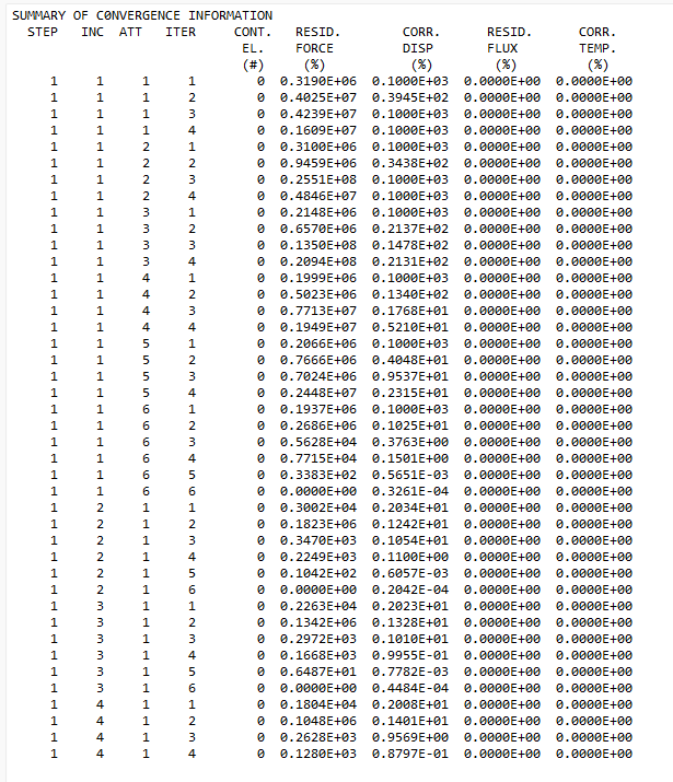
I face convergence issues with Calculix (Paradiso) solver, with model create with PrePoMax.
I have a static step with centrifugal load, and I am using NLGEOM option.
Is it the same wing as in your previous thread ? I’ve tried with the geometry from there, and it works. I used much lighter mesh; yours seemed too dense with C3D20 elements, so I used C3D8R (of course, it can always be refined if needed).
Nlgeom often causes non-convergence, especially in CalculiX. Because of that, it’s better to avoid it when it’s not absolutely necessary. And at least disable it for debugging and see if the results without it make sense.
Yes, it is the same solid geometry as other thread.
I used parabolic hex éléments since I need to shell meshes (skins) over the solid core (this is a simplified model I shared). And only parabolic quads types are supported by Calculix for composites Shell sections (so need 20 nodes hex for compatibility).
Do you think my convergence issue is caused by this kind of dense parabolic Mesh ? (With nlgeom)
Btw, the nlgeom option is required since i need to apply a second step with aérodynamic load . (else, just the aero load forces without centrigugal force lead to unrealistic excessive deflection).
Maybe you could replace them with thickened solid layer(s) to avoid this limitation. Or just use tie constraints to connect mismatching meshes.
Fully integrated second order elements can be problematic in terms of volumetric locking (happens for nearly incompressible materials), contact and large deformations leading to mesh distortions. C3D8R elements are much lighter, robust and usually sufficient if you use enough of them (after a mesh convergence study).
Btw. for such foam material, you may need nonlinear elasticity if strains exceed around 5%.
Ok, I see, you need it to stiffen first (the material is very soft). If your mesh is reasonable, there are no singularities, the loads are realistic and there are no other issues in a linear run while the nonlinear one still doesn’t converge, you can try adjusting the solver controls. But try changing the mesh first, this is likely to help.
Thanks again for your help.
It works now by changing solid mesh from C3D20 to C3D8(R), i.e. analysis converges with NlGeom as True.
Problem is that, if I want to integrate the skins to this core (two shell meshes, as parabolic elements, linked to solid mesh through TIE constraints), the analysis does not converge anymore.
I used shell sections of 0.2mm of each skin. I uses S8R elements for shells since I will need later on to specify composites properties (but for this simple test, I just use simple constant shell section.
Tie constraints take the shell thickness into account.
However, rigid body constraints used with shells and Nlgeom are a known cause of non-convergence: Known CalculiX limitations
So you should avoid one of those ingredients. Usually the best way is to replace shells with equivalent solid layers. Or to replace rigid body constraints.
Thanks again for your help.
I was able to replace shell meshes (for skins) by solid mesh elements, as advised.
I then have C3D8R for both core and skins (fully solid, no Tie constraints), and the static analysis with NlGeom converges well. I use composites solid sections on the solid mesh for skins.
Problem is that results are very stiff (1mm max deflection under 5 N load force on tip). Some measurements shown 15mm instead.
The skin solid mesh has one row of hex elements per layer. Each skin has three layers (one is partial / reinforcement), 0.1 mm thick each. It leads to bad quality elements, and I am wondering if it would be the root cause for this unexpected result.
What do you think ?
Refining the mesh is always a good idea in such cases. Especially since C3D8R elements are good, but you need at least 4-5 od them through the thickness to avoid spurious deformation effects such as hourglassing.
However, I would also have a closer look at the material properties. You may need to find a better source of them to match the experiment. Foams are typically modeled as nonlinear elastic - CalculiX has both hyperelastic and hyperfoam material models, but you need proper constants for them either from calibration with test results or from the literature.