Regarding the presentation in the below, the model interest is the Bracket which shown and display the mises stress, however in case the model interest is the tube, how to set the parameter, so that I can determine how much stress for the tubes.
Summary:
How to set the parameter for primary model and secondary model?
Primary model: Able to display the Von mises stress, displacement, etc.
Secondary model: is just load distributor only.
In this analysis both parts are deformable so you can check their stresses. However, you could also make one part (the one for which you don’t need the stresses) rigid using a rigid body constraint: How to treat a body as rigid?
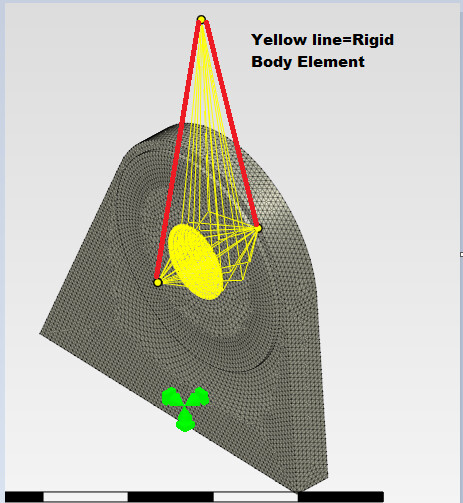
Dear Sir, Regarding implementation of Rigid Body, yellow line is existing rigid body (this is doable as it is available already in Prepomax). However, is it possible to connect all 3-reference point connected by another Rigid body element (red line)? I need to provide upper rigid body to consider the load moment distance. Please see attached snap shot
Dear Sir, thank you so much that’s brilliant idea . Now I understand that reference point is not just a point, but it actually mimic a rigid body element where able to transfer the load, even it is not connected directly to the model or another rigid body element.
Thank you always sharing your brilliant ideas.
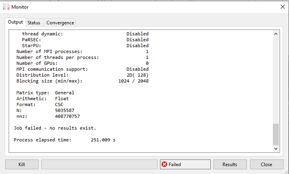
Dear Sir, I apply in the model I created; however I cannot find any reason why in my model does not run and warning message occur. I did my trial in the model you send and it works very well. But in my model Job failed-no results exist.
Do I need to apply sub modeling since I divide the model into 2. This is because I have load on left side and right side, in addition to the load moment at upper side Fz?
Kindly see the attached model for your details of my model in the following message.
Thank you and really appreciate for your kind help.
Ok sir, thank you for your kind advice I will do that. For the mean time Sir I just make my mesh using BASIC and not use ADVANCED setting. Then my file is become small.
See attached file sir. 3D_LUG_CUT-Mid_Static_SmallFile.pmx (314.3 KB)
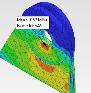
Dear Sir, regarding the Rigid Body Element, for my reference and comparison I made a model where the actual pin is model. My purpose is to compare the result of Rigid Body Element result to actual 3D solid model so that I have further analysis.
Therefore in this case I use contact. After run the basic analysis there is very big difference for Von mises stress. Appreciate sir any helpful advise.
Kindly see the attached model. 3D_LUG_Contact.pmx (540.0 KB)
Thank you and really appreciate for your kind help.
Contact requires very dense (locally) meshes to provide accurate results. This mesh is way too coarse. Check e.g. this tutorial: https://www.youtube.com/watch?v=pEktnro0G0k
To simplify the analysis in which the pin is modeled, you could make it rigid (by applying a rigid body constraint to it). That would be something between the case with a deformable pin and with only rigid body constraints replacing it. Another way would be to model the pin as a rigid surface (shell) and connect a rigid body constraint to it to provide this arm for loading. The case with only rigid body constraints might be too simplified to provide good results. Especially since the actual pin doesn’t pull the bottom part of the hole (you could split it for rigid body constraints or use the compression-only constraint).
Also, you need some interaction (tie or contact) between the two parts of the lug in the case without contact. As you can see in the screenshot you attached, there’s an interference and separation between the parts.
Dear Sir, I try hard to visualize this, however I cannot, appreciate if you could give me a hint like a simple sketch only will be very helpful.
Thaks a lot.
Try non-linear analysis. In this case, deformation can be large, therefore the stress to. With material non-linearity, the large deformation won’t cause large stress values
Thank you Sir @FEAnalyst . I appreciate sharing your ideas, beyond your technical expertise Sir, I just want to thank you for being such a generous and supportive mentor in the FEA world. Your willingness to answer my questions and share your knowledge has been invaluable. I am gaining and feel much more encouraged and not give up in the FEA world i.e. tackling complex analyses if there is someone in the community like you. Thanks to you.
Dear Sir @FEAnalyst , Sorry I came back here. I miss very important question in your model. Would I know how did you connect the upper reference point since there is no Rigid Body assigned? Thanks…