I’m working on modelling pretensioned membrane structures in PrePoMax and seeking guidance on proper setup methodology. Despite trying various approaches, I’m not achieving effective pretensioning results and would appreciate input from experienced users.
Typical Case Study Parameters
Geometry:
Rectangular membrane: ~5m × 10m (aspect ratio 1:2)
Thin section: 1-2 mm thickness
Material: Flexible textile (E = 1000-2000 MPa range)
A lot of that (especially BCs) depends on the real-life scenario that you want to model. Have you seen this tutorial ? https://www.youtube.com/watch?v=-M2BOHHkUf4 It shows how to model preload for a similar setup and includes analytical verification. Frequency analysis allows you to easily check if it’s correct - you should notice the change in natural frequencies when preload is included.
Force control (any type of load that you can assign to edges and conveniently define its magnitude using the inherent units - force or force per unit length) is the easiest way. Pulling with displacement control (if used properly) is better for convergence in nonlinear steps. Thermal load is rather old-fashioned way (also sometimes used for bolts but CalculiX has bolt pre-tension feature so thermal load is not needed).
Thank you for the feedback. I found the way the boundary conditions for the anchors were defined to be very interesting, as it’s a combination I hadn’t tried before. I’d like to add an observation: in this case, I want to determine how much pre-stress is needed to reduce the maximum displacement caused by Gravity + WindLoad (as Uniform pressure). My approach would involve:
Step 1: Define the anchors as shown in the video, but only on the short sides, as I intend to tension the shell in one direction (assuming Y is the longitudinal direction). Also, include Gravity + WindLoad as the loads.
Step 2: Use the same anchors, but include only Normal-Edge Shell as the load on the short edge.
Step 3: Set up a frequency-step with the perturbation option enabled.
However, I’m unsure if this method is correct, and I cannot fully grasp the following points:
Understanding the maximum displacement due to self-weight + Wind Load.
Why doesn’t tensioning seem to reduce displacement?
My goal is to calculate how much tension should be applied to the short supports to achieve the desired displacement, which should be less than the displacement caused by Gravity + wind load.
Any suggestions will be much appreciated, as done up to now.
Many thanks.
Do you have any nonlinearities in your analysis ? You should have Nlgeom enabled in the sequence of static steps but it’s also important to account for plasticity when modeling preload. The intricacies of multistep analyses are explained here (especially point 4 is important in this case): Understanding multistep analyses
Typically, preload and so-called “dead loads” (gravity) are applied in the first steps and then there are operational loads introduced in the subsequent steps. Frequency step is not always necessary, only if you want to check the influence of the preload on natural frequencies of the structure. If the perturbation option is enabled, it takes the state of the model from the previous static step.
Thank you for the clarification on frequency analysis!
You’re right - frequency step isn’t necessary for my specific goal. I’m focused on displacement reduction under operational loads, not frequency validation.
Regarding Nlgeom and step sequence: Based on your multistep analysis guidance, I think my approach needs correction. Currently I’m seeing counterintuitive results - pretensioning actually increases displacement instead of reducing it.
Step 2: Add pretensioning with Nlgeom ON (should reduce displacement from Step 1)
Key questions:
Is Nlgeom absolutely critical for thin membrane pretensioning effectiveness? (thickness = 1.65mm, span = 10m)
Should pretensioning forces be applied as incremental in Step 2, or as total values?
For membrane structures, is there a minimum pretensioning magnitude threshold below which no stiffening effect occurs?
Current issue: With elastic material and thin geometry, I suspect the membrane isn’t developing sufficient membrane action to benefit from pretensioning - it’s behaving more like a flexible plate in bending.
The Nlgeom suggestion makes perfect sense for this case, as thin membranes should exhibit significant geometric nonlinearity under tension.
Will implement Nlgeom ON and test the corrected step sequence. Thank you for pointing toward the multistep analysis fundamentals!
Isn’t pretensioning supposed to happen before operational conditions such as wind load ? The loading sequence should correspond to real life situation.
You’re absolutely right about loading sequence! Real-life: pretensioning happens during installation, then operational loads. My sequence was backwards.
Corrected approach:
Step 1: Pretensioning only (simulate installation)
Element type insight: This is crucial! I’m currently using shell elements (which have bending stiffness). For pure membrane behavior, should I switch to membrane elements instead?
Key question: For pretensioned textile structures, which element type gives more realistic results:
Shell elements (current) - include bending stiffness but may not capture membrane action properly
Membrane elements - pure tension/compression, no bending stiffness
The fact that I’m seeing “flexible plate in bending” behavior suggests shell elements might be dominating through flexural response rather than membrane tension.
Yes, membrane elements make sense in such cases. They are used to model very thin structures, often fabrics or coatings or something like a balloon. They have no bending stiffness, they only carry in-plane forces. In CalculiX, they aren’t true membrane elements just like shells aren’t true shells - they are internally expanded to solids. Membrane elements have hinges at all their nodes to eliminate the bending stiffness. But still, they can be used successfully in various applications involving particularly thin members.
Following up on our membrane elements discussion - I’m running into some implementation challenges in PrePoMax.
Issue encountered: When trying to switch to membrane elements, I get this CalculiX error:
*ERROR reading *MEMBRANE SECTION: *MEMBRANE SECTION can only be used for membrane elements. Element 1 is not a membrane element.
Surely I’m missing something in the setup process.
Request: Since membrane elements seem problematic, I was wondering if you might have a moment to glance at my shell element configuration instead? I’ve taken the liberty of attaching the .pmx file to this post, but please feel free to ignore it if you’re too busy.
If you do have time to take a look, I would be extremely grateful for any insights on:
Whether my current shell setup seems reasonable for thin membrane behavior
Confirmation that Nlgeom + proper step sequence should be sufficient for effective pretensioning
Any obvious setup issues you might notice that could improve pretensioning effectiveness
I completely understand if you don’t have time for file reviews - your guidance in this discussion has already been incredibly helpful and educational. Any feedback would be genuinely appreciated, but no pressure whatsoever!
Apart from assigning a membrane section, you also have to change the type of elements from S to M (membrane) ones. Right-click on the part and select Edit:
It would be better to use quad elements. In the Geometry tab, you can add Shell Gmsh mesh item and set 2D meshing algorithm and Recombination in such a way to get quads.
Is it intentional that in the first step there’s no U1 boundary condition?
You’re absolutely right: even though I intentionally left U1 without any boundary condition to avoid tensioning along the X direction, the physical behaviour of the membrane still leads to deformation in that direction. My goal was to minimize this transverse deformation and focus the pretensioning along the longitudinal Y axis. I realize this is a bit of an idealization, but I wanted to test whether such behavior could be approximated.
Also, thanks for the clarification regarding membrane elements. I agree—PrePoMax isn’t always the most intuitive when it comes to discovering hidden settings. I only realized I could change membrane parameters by manually clicking through each item in the dropdown menus—not exactly user-friendly, but manageable once you know where to look definitely.
Here’s what I’ve done so far (PrePoMax v2.3.0):
Assigned the section as a membrane
Changed the element type from S to M (membrane) - what’s the difference between M3D8 vs M3D8R?
Set pretensioning as Step-1
Used a Quad-mesh (thanks to Matej Borovinšek’s video here)
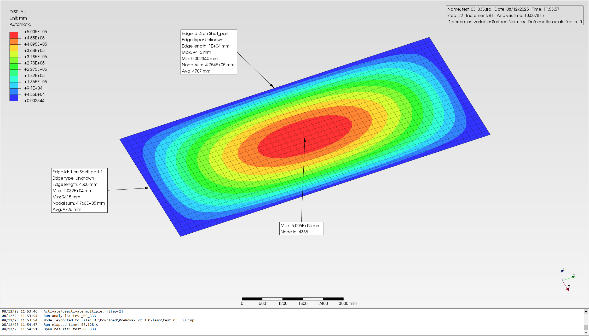
However, the analysis fails, and the only result I get—displacement—is physically unrealistic. I’m attaching two simple screenshots below to illustrate the issue.
The latter uses reduced integration - less integration (Gauss) points. It’s a long story when it comes to element selection but, in short words, R might be better here. You can compare both though once you have the correct setup.
You are using the Pre-tension load. This is meant for solid bolt models and applied in a different way (to two compounded halves of the bolt). You should use regular loads such as traction/shell edge load instead.
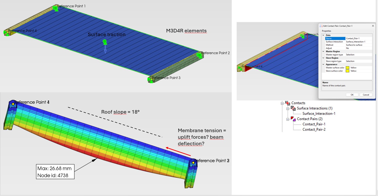
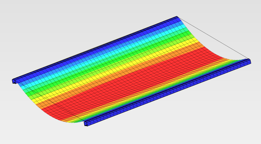
If membrane has only tensile stresses, I do not see how the membrane is appliying so much forces in the -Z direction to the beams and very little though the center of the membrane.
I tried different configuration of Constraints / Contact between membrane and the beam and did succed.
Do you have any idea how to magane solid to membrane interactions?
Can you share the .pmx file ? Is that tied contact ? Did you try tie constraints too ? And shells for comparison ? FYI, there’s also tension-only material in CalculiX.
Here, I used tied contact at a narrow surface around the membrane. But it’s important to consider whether you need to define the connection only at the edges (and perfectly bonded) or maybe at an area as shown above (and perhaps not tied everywhere).
Thank you all for continuing to share ideas, solutions, and procedures — it’s truly valuable to follow your reasoning and exchanges.
I would also like to suggest, if possible, sharing the analysis models you are working with (especially Hedo’s, though the full-framed case would also be interesting to inspect), as studying the files can teach a great deal even before asking questions that might otherwise take several steps to frame the best solution.
For instance, I’m focusing on one or two steps:
pretensioning
wind load + dead load, to evaluate the resulting displacement and stress forces.
Thanks again for the generosity and collaborative spirit that make this discussion so inspiring and insightful!