I am a new user of CalculiX & PrePoMax, previously an Abaqus user.
I’m trying to create a simple model for a Modal Dynamic analysis. I added membrane elements (M3D4R) to the bottom surface of the model to get accurate surface stress and strain results (I previously used a thickness of 0.001 mm in my ABAQUS models).
During the frequency analysis, I found an abnormal behavior.Compared to the benchmark model without the membrane, the frequency increases significantly as the membrane thickness decreases.
Frequency results with different membrance thickness as below.
Keep in mind that membranes and shells in CalculiX aren’t true 2D elements - they are internally expanded to solids and this often leads to issues making it safer to use 3D elements right away if possible. PrePoMax has a Thicken Shell Mesh tool to make it easier.
Thank you for your suggestions and for explaining that membranes and shells in CalculiX are not true 2D elements.
I’ve studied documentation to understand how 2D elements are expanded to solids.
I did some tests with and without an offset, using different element type, results as below.
In this case, the offset had no effect. However, since 2D elements are expanded into solid elements, I still consider using an offset for future models to avoid overlap and some potential issues.
The results for M3D4R and S4R (expanded to C3D8R actually) showed increased stiffness, which was consistent with the results from creating a solid mesh with the thicken shell mesh tool (and setting it as C3D8R).
Using S4 (expanded to C3D8I actually) and solid mesh C3D8I showed strange results in modes 7 and 8.
The results for M3D4 and C3D8 were normal.
Using M3D4 element for membranes added to the surface of solid elements is a good choice. However, since the 2D elements are actually expanded to solid element, there should be some difference from the in-plane stress. I will test this part later.
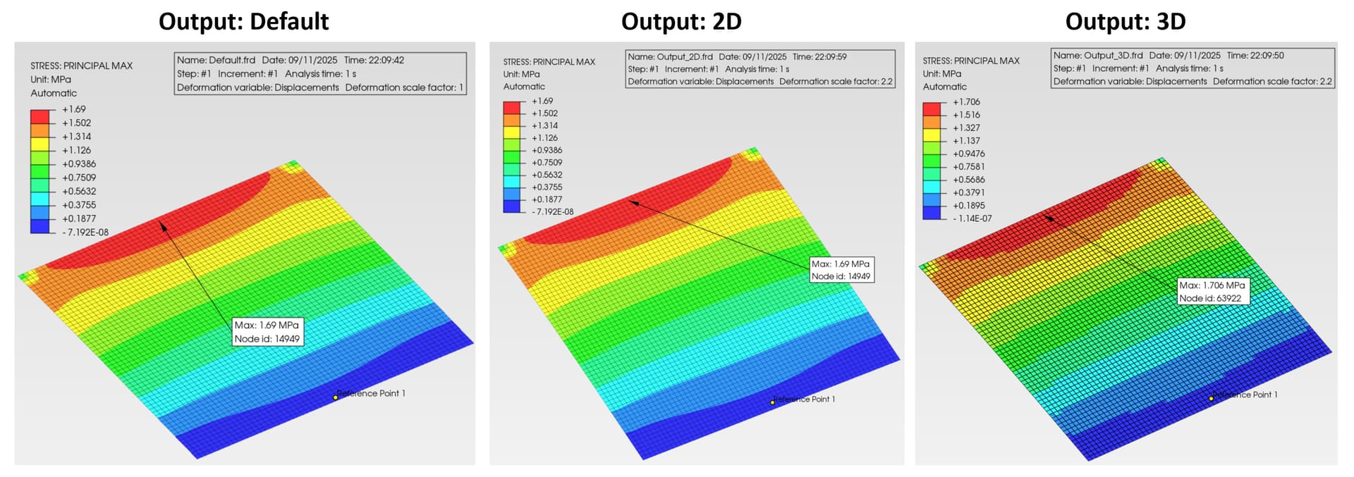
It seems that the default setting of EL output is the same as output=2D, and the contour of output=3D is not smooth.
Although S33, S13, and S23 have values, they are very small and can be ignored.
To clarify, here’s a quote from the CalculiX User’s Manual:
If OUTPUT=2D the fields in the expanded elements are averaged to obtain the values in the nodes of the original 1d and 2d elements. In particular, averaging removes the bending stresses in beams and shells. Therefore, default for beams and shells is OUTPUT=3D, for plane stress, plane strain and axisymmetric elements it is OUTPUT=2D.
It doesn’t mention membranes, but for them the default is 2D since they don’t have a bending stiffness.
Interesting. I haven’t tried membranes in CalculiX, but what happens if you use them along with a shell structure? Is it possible to ask for 2D output for the membranes, but 3D output for the shells? Or for any similar scenario in which you want 3D output but use membranes for specific structures
Good question. I checked it and if you have both shells and membranes then it uses 3D output by default. Also, it’s not possible to have both 2D and 3D output in the same analysis even if you do something like this: