Dear Forum,
As you may have seen over the past couple of days, I have been trying to complete simulations of several very geometrically primitive aircraft wings.
As I try to simplify my CAD geometry, the behavior of the simulation results becomes more and more unexpected.
In the screenshot below, I split the aircraft wing into upper and lower skins. The wing base is fixed, .1N upward load at wing tip, and the 2 spars are constrained to the lower wing surface using TIE constraints. I have tried applying the TIE connection between parts AND between surface and edge. I get the same results.
TIA,
–Neal
Please try running a frequency analysis. This should reveal issues with connections between the parts/meshes. It might be a matter of a too coarse mesh (like with contact here: Assistance with Specifying Deflection Behaviour - #4 by FEAnalyst) or too low tolerance in the tie constraint definition. But it’s hard to say without checking the model.
1 Like
Thank you. I will go ahead and do this.
Dear Forum,
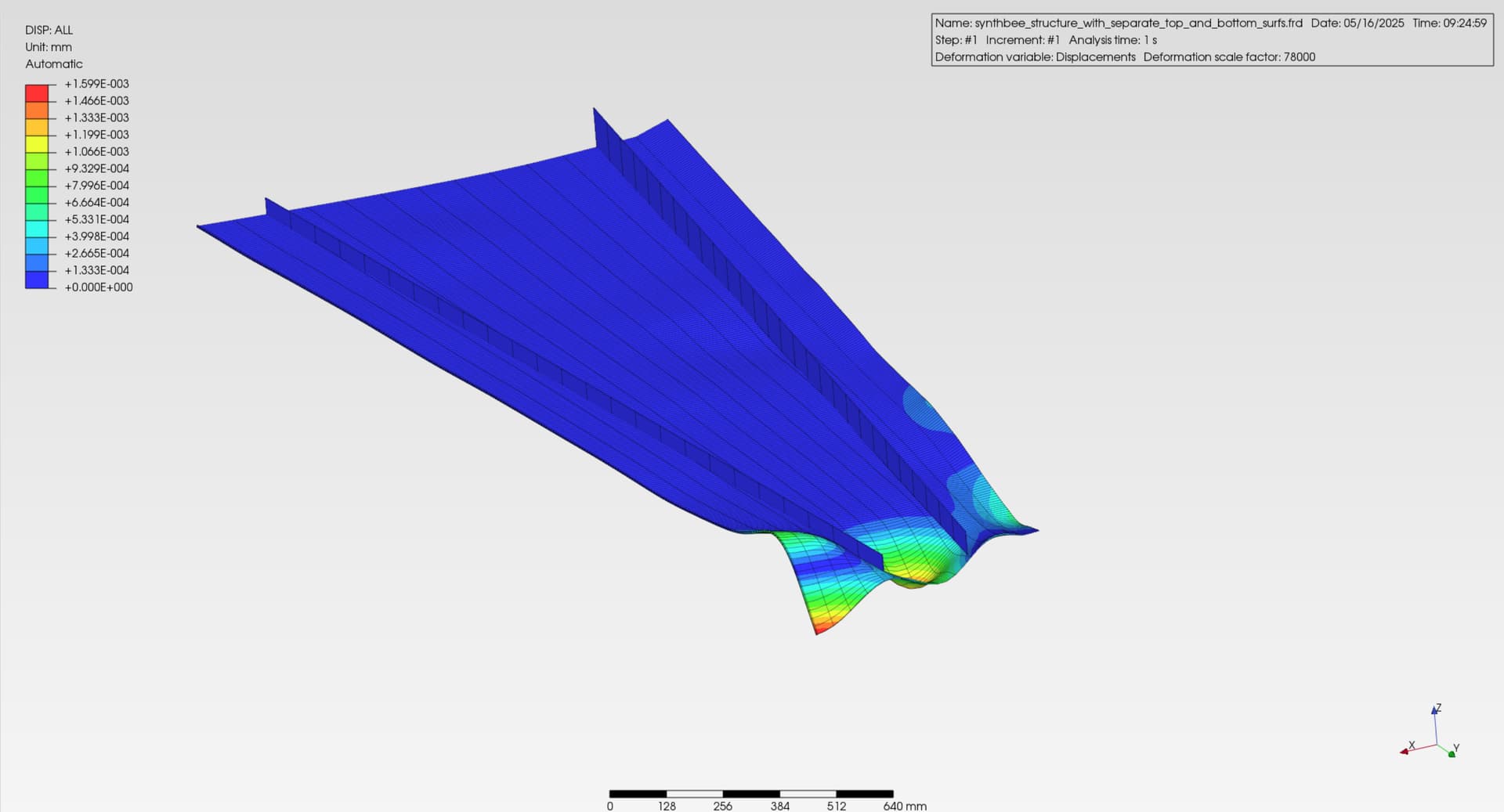
So I just completed a frequency analysis and this the the result in Mode #1.
Is this result telling me that the left rib showing all of the deflection is NOT connected to the lower wing skin surface?
TIA,
–Neal
1 Like
Yes, you can animate this mode shape to see how it deforms individually. As I said, refine the mesh and adjust the tolerance.