Dear community,
I’m simulating the compression of a cylindrical sample made of a material X. In the lab, I prepared 20 identical cylinders with known initial diameter and height. Each cylinder was compressed only once under a specific load: 0.3 N, 1 N, 3 N, or 5 N. After compression, I re-measured the height and captured the 3D morphology of each sample. The final height is my main parameter of interest.
Based on the initial diameter, I calculated the corresponding initial pressure and used this to define a set of values representing the plastic deformation behavior of the material.
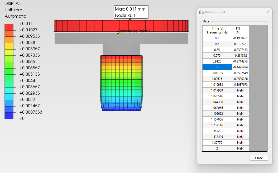
In my simulation testbench, I model a single cylinder and apply a Surface Traction to the top surface. Using this setup, I’m getting final height results that are reasonably close to the experimental data — within ~20% error for lower compression forces.
The issue I’m facing is with the resulting shape of the deformed cylinder.
In my current setup, the applied load is restricted to the initial top surface area of the cylinder. As the cylinder expands radially during compression, the load doesn’t spread over the newly expanded surface. This causes the original top face (which remains the only loaded area) to sink into the material, resulting in a donut-like shape (without the hole).
I’d like to simulate a compression setup that:
-
Takes into account the increasing contact area as the cylinder expands;
-
Applies the force realistically over the entire top surface, even as it grows outward during compression.
Is there a way in PrePoMax (or CalculiX) to model this more accurately?
Should I be using contact with a rigid plate instead of applying direct traction? Or is there another technique to dynamically apply the force over the full, deformed surface?
Any advice would be greatly appreciated!
Thanks in advance.