Node area inside a cylinder

Hello,

i am trying to create a reference point on a node area inside a cylinder.

How can i perform this? On a flat surface, I can do this in CAD using ‘split surface’, for example. Is it also possible to do this in PrePoMax?

Example another FEM software:

Shorten the Z-width to between 31 mm and 47 mm, and the Y-height to between 140 mm and 166 mm.

PrePoMax File here:

Many thanks in advice!

I can’t access it, there’s an error:

Error
The URL doesn’t have the correct format.

But can you share the .pmx file too ?

However, you should partition the surface in CAD software to get such a node set on a uniform surface patch. I can provide some tips on how to do it in FreeCAD if you want.

new link:

https://fileport.io/VTatYxGKZPVW

I am working with inventor but freecad also fine.

Many thanks!

Ok, but this .pmx file doesn’t include CAD geometry, only the mesh. Do you have those parts in STEP too ? Anyway, here’s how it can be done in FreeCAD: https://wiki.freecad.org/FEM_Geometry_Preparation_and_Meshing#Partitioning_faces_of_solids_with_datum_planes

my fault here the STP files:

https://fileport.io/eU8DNyQLLpfP

To create the split surface like this its easy:

The problem is more when the contact area is like this:

It is not possible to select nodes based on the size of the bounding box. The best way is to create a split geometry.

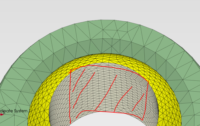
There is also a way to select nodes manually on the mesh by clicking the More button in the Set Selection window and using commands from the FE mesh-based selection. There, you can add or subtract nodes by area selection.

2 Likes

Thanks! I already found a workaround for the Split Face feature in Inventor.

I created a circle in 2D geometry and then used two offsets to split the other faces.

Indeed it’s quite a lot of manual work but doable with the aforementioned approach in FreeCAD:

1 Like