Well, even if the part looks mashable with hexa, will be a pain to make it using PrePoMax by the moment. Pay attention that a big part of the stress for a connecting rod is normally due to the bolt preload (and you don´t have modeled the holes), and probably in other places with some radius that you have deleted to be able to mesh with hexas… so will be a waste of time that meshing.
Due to the shape of your model and partitions, some hexas will be severely distorted/skewed (in the past I fount that includind some radius and draft angles lead to better elements shapes, but you will need to be very proficient with the partitions and a very powerfull mesher like Siemens NX or Abaqus CAE…)
Even if you still want to mesh it, I would suggest you work with a quarter model, and then use symetric bc, or just make a mirrowing of the mesh to get the full model (don´t know if it can be done in Prepomax by the moment).
Well formed second order tets with some local refinement will be better/cost effective for that part.
The goal has ever been to test PrePoMax mesh capabilities (pro and cons); even using Freecad to split volumes is not so straight foward
(note I used Hyperworks for years )
You spoke about mirroring: not sure pmx allows such capability
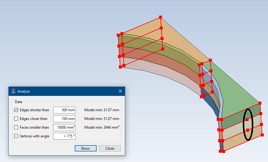
Because you have some additional edges in those compounds. You can find them by searching for “edges shorter than” in Prepomax and looking for additional endpoints.
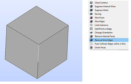
In Salome, for example, these can be automatically found and merged by using the “Remove Extra Edges” tool. I don’t know if FreeCAD has a similar tool.
Unfortunately not and it would have to be done manually by breaking into wireframe there.
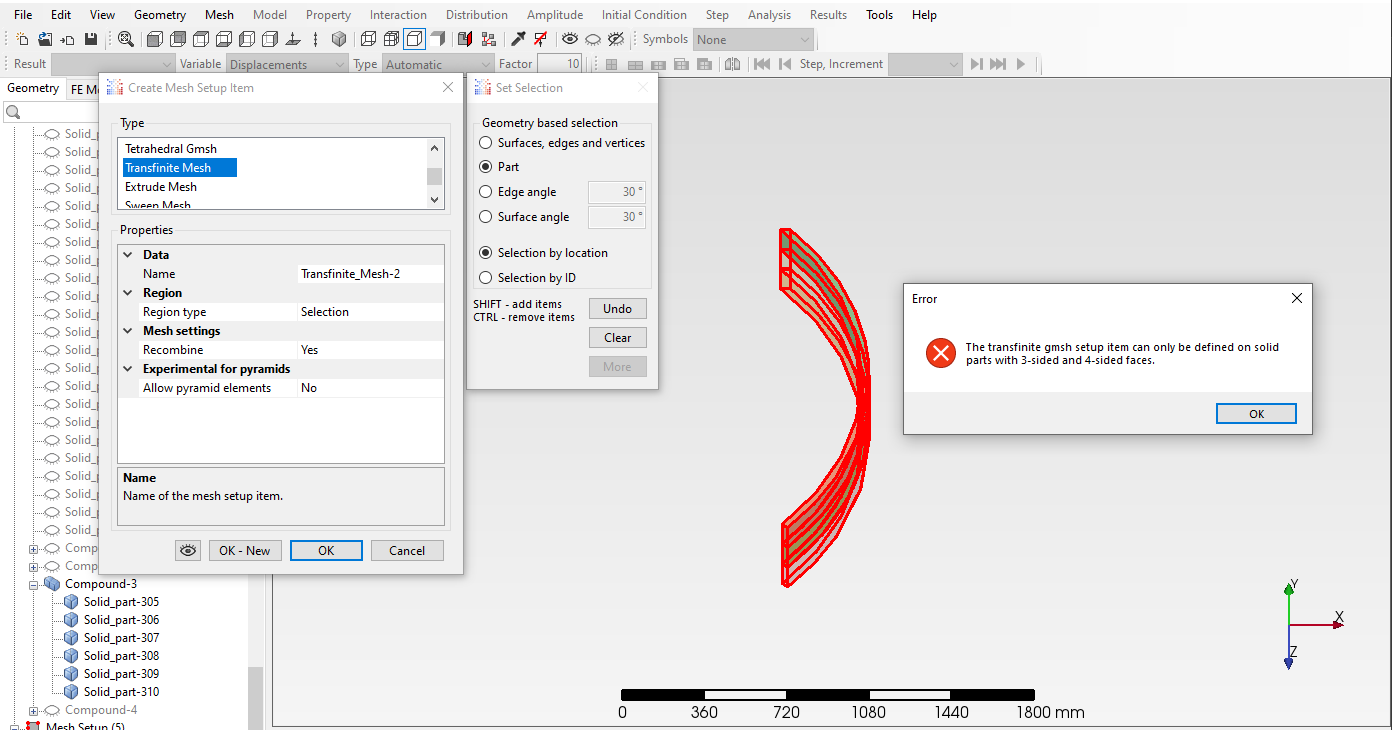
The rules of transfinite meshing (5 or 6 faces with 3 or 4 edges each) are strict and if you see an error message like that, you have to look for extra faces and edges and remove them in CAD software or with the defeaturing tool.
How do you proceed in Freecad? (looked for by i missed)
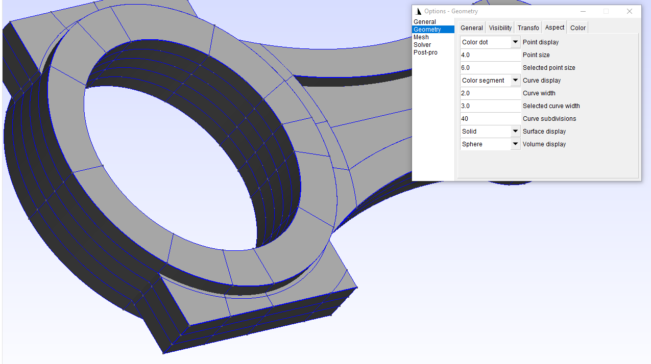
Agree but i was not aware on how to check it in pmx
yes it is on the pipe; i need to train to get the good way to control the (edge) discretization to that the mesh is fully conincident (including bias use); i know the number of layers can easily by specified
here after the Freecad file to let anybody to play with bielle0.zip (1.5 MB)
In practice, that would be a lot of manual work. In this simple case, it’s way easier to just split the volume where the redundant vertex is. In other basic cases it may also make sense to recreate the part.
I’ve identified additional edges and i performed extra-cuts; I’ve cheked in both freecad and pmx prior to import the step file and it looked “good”, but actually still having issues.
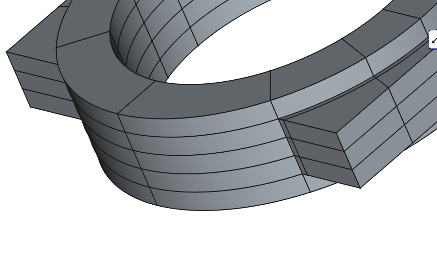
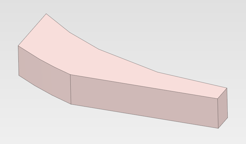
I can note some volumes seem “unstuck” i.e. not to fully coincident -see pmx_import.png);
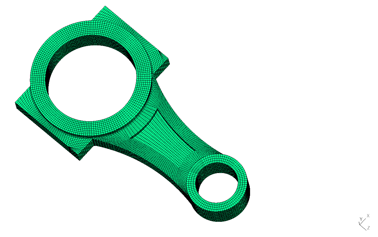
seems correct in both freecad (see freecad.png) and gmsh (see gmsh.png)
does it come from the part display?
i had a look to the settings to see if any import tolerance can be changed, but it seems to be automatic, isn’t it?
So the cutting process is leading to CAD issue and i cannot fix it for now (using freecad); years ago i tested Salomé, but I found it “non-intuitive” compare to other (commercial) tools …
Thanks Jakub for your help on the different topics; i’ve now a better understanding on how to proceed and this example has been (for me at least) very usefull.
I would ask to PrePoMax team if it’s possible to add the list of the elements involved in the error message (see post 1): with a bit more than 200 volumes, it is not straight forward to identify which one(s) must be modified.
My goal has ever been to used a 100% use of transfinite (i.e. fully automatic meshing); however it’s generally the case for simple geometries.
This example has to be reworked
since “cuts” come from how i used freecad; some of them can be avoided
the quality of the elements might be improved by splitting differently and by using a bias (need to check such option)
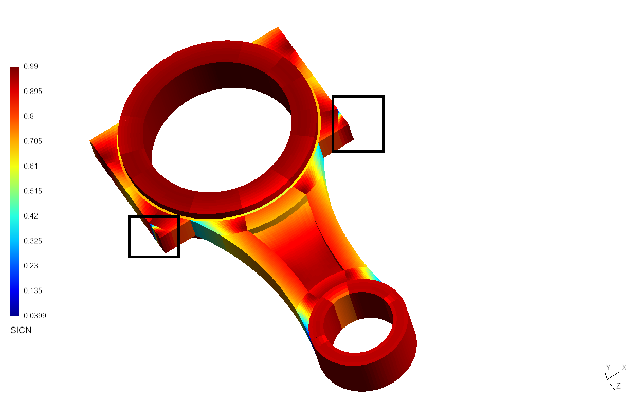
I also tested the gmsh export which seems to work fine; i used gmsh to test the elements quality (i think elements Jacobian are calculated - see picture)