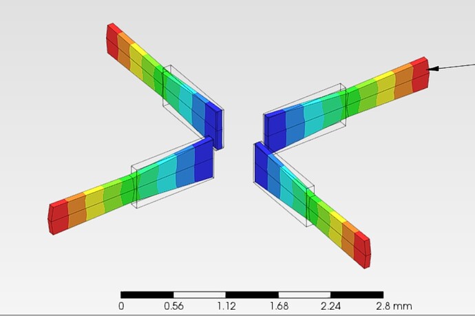
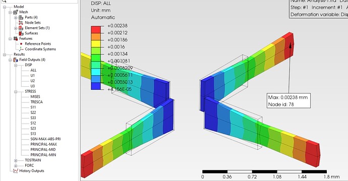
Hi Matej,
When a traction is applied to a set of faces in which only some of the nodes are under a Cylindrical coordinate system transformation , Prepomax interrupts and closes.
By other hand, I find the way the cylindrical coordinate system is defined really confusing. From my point of view, user should only be requested to input two point as in the manual.
*Node
1, 1.00000000E+000, 0.00000000E+000, -1.00000000E+000
2, 1.00000000E+000, 1.00000000E+000, -1.00000000E+000
3, 5.00000000E-001, 1.00000000E+000, -5.00000000E-001
4, 5.00000000E-001, 0.00000000E+000, -5.00000000E-001
5, 1.00000000E+000, 5.00000000E-001, -1.00000000E+000
6, 7.50000000E-001, 1.00000000E+000, -7.50000000E-001
7, 5.00000000E-001, 5.00000000E-001, -5.00000000E-001
8, 7.50000000E-001, 0.00000000E+000, -7.50000000E-001
9, 7.50000000E-001, 5.00000000E-001, -7.50000000E-001
10, 8.12500000E-001, 1.00000000E+000, -8.12500000E-001
11, 8.12500000E-001, 7.50000000E-001, -8.12500000E-001
12, 0.00000000E+000, 0.00000000E+000, 0.00000000E+000
13, 8.12500000E-001, 8.75000000E-001, -8.12500000E-001
14, 8.12500000E-001, 6.25000000E-001, -8.12500000E-001
15, 7.50000000E-001, 2.50000000E-001, -7.50000000E-001
16, 6.25000000E-001, 5.00000000E-001, -6.25000000E-001
17, 5.00000000E-001, 2.50000000E-001, -5.00000000E-001
18, 6.25000000E-001, 0.00000000E+000, -6.25000000E-001
19, 6.25000000E-001, 2.50000000E-001, -6.25000000E-001
20, 1.00000000E+000, 2.50000000E-001, -1.00000000E+000
21, 8.75000000E-001, 5.00000000E-001, -8.75000000E-001
22, 8.75000000E-001, 0.00000000E+000, -8.75000000E-001
23, 8.75000000E-001, 2.50000000E-001, -8.75000000E-001
24, 1.00000000E+000, 7.50000000E-001, -1.00000000E+000
25, 8.75000000E-001, 1.00000000E+000, -8.75000000E-001
26, 7.50000000E-001, 7.50000000E-001, -7.50000000E-001
27, 8.75000000E-001, 7.50000000E-001, -8.75000000E-001
28, 6.25000000E-001, 1.00000000E+000, -6.25000000E-001
29, 5.00000000E-001, 7.50000000E-001, -5.00000000E-001
30, 6.25000000E-001, 7.50000000E-001, -6.25000000E-001
31, 7.50000000E-001, 6.25000000E-001, -7.50000000E-001
32, 6.87500000E-001, 7.50000000E-001, -6.87500000E-001
33, 6.25000000E-001, 6.25000000E-001, -6.25000000E-001
34, 6.87500000E-001, 5.00000000E-001, -6.87500000E-001
35, 6.87500000E-001, 6.25000000E-001, -6.87500000E-001
36, 7.50000000E-001, 8.75000000E-001, -7.50000000E-001
37, 6.87500000E-001, 1.00000000E+000, -6.87500000E-001
38, 6.25000000E-001, 8.75000000E-001, -6.25000000E-001
39, 6.87500000E-001, 8.75000000E-001, -6.87500000E-001
40, 5.62500000E-001, 1.00000000E+000, -5.62500000E-001
41, 5.00000000E-001, 8.75000000E-001, -5.00000000E-001
42, 5.62500000E-001, 7.50000000E-001, -5.62500000E-001
43, 5.62500000E-001, 8.75000000E-001, -5.62500000E-001
44, 5.00000000E-001, 6.25000000E-001, -5.00000000E-001
45, 5.62500000E-001, 5.00000000E-001, -5.62500000E-001
46, 5.62500000E-001, 6.25000000E-001, -5.62500000E-001
47, 7.50000000E-001, 1.25000000E-001, -7.50000000E-001
48, 6.87500000E-001, 2.50000000E-001, -6.87500000E-001
49, 6.25000000E-001, 1.25000000E-001, -6.25000000E-001
50, 6.87500000E-001, 0.00000000E+000, -6.87500000E-001
51, 6.87500000E-001, 1.25000000E-001, -6.87500000E-001
52, 7.50000000E-001, 3.75000000E-001, -7.50000000E-001
53, 6.25000000E-001, 3.75000000E-001, -6.25000000E-001
54, 6.87500000E-001, 3.75000000E-001, -6.87500000E-001
55, 5.00000000E-001, 3.75000000E-001, -5.00000000E-001
56, 5.62500000E-001, 2.50000000E-001, -5.62500000E-001
57, 5.62500000E-001, 3.75000000E-001, -5.62500000E-001
58, 5.00000000E-001, 1.25000000E-001, -5.00000000E-001
59, 5.62500000E-001, 0.00000000E+000, -5.62500000E-001
60, 5.62500000E-001, 1.25000000E-001, -5.62500000E-001
61, 1.00000000E+000, 1.25000000E-001, -1.00000000E+000
62, 9.37500000E-001, 2.50000000E-001, -9.37500000E-001
63, 8.75000000E-001, 1.25000000E-001, -8.75000000E-001
64, 9.37500000E-001, 0.00000000E+000, -9.37500000E-001
65, 9.37500000E-001, 1.25000000E-001, -9.37500000E-001
66, 1.00000000E+000, 3.75000000E-001, -1.00000000E+000
67, 9.37500000E-001, 5.00000000E-001, -9.37500000E-001
68, 8.75000000E-001, 3.75000000E-001, -8.75000000E-001
69, 9.37500000E-001, 3.75000000E-001, -9.37500000E-001
70, 8.12500000E-001, 5.00000000E-001, -8.12500000E-001
71, 8.12500000E-001, 2.50000000E-001, -8.12500000E-001
72, 8.12500000E-001, 3.75000000E-001, -8.12500000E-001
73, 8.12500000E-001, 0.00000000E+000, -8.12500000E-001
74, 8.12500000E-001, 1.25000000E-001, -8.12500000E-001
75, 1.00000000E+000, 6.25000000E-001, -1.00000000E+000
76, 9.37500000E-001, 7.50000000E-001, -9.37500000E-001
77, 8.75000000E-001, 6.25000000E-001, -8.75000000E-001
78, 9.37500000E-001, 6.25000000E-001, -9.37500000E-001
79, 1.00000000E+000, 8.75000000E-001, -1.00000000E+000
80, 9.37500000E-001, 1.00000000E+000, -9.37500000E-001
81, 8.75000000E-001, 8.75000000E-001, -8.75000000E-001
82, 9.37500000E-001, 8.75000000E-001, -9.37500000E-001
**
** Elements ++++++++++++++++++++++++++++++++++++++++++++++++
**
*Element, Type=S4, Elset=Shell_part-1
1, 5, 75, 78, 67
2, 75, 24, 76, 78
3, 78, 76, 27, 77
4, 67, 78, 77, 21
5, 74, 71, 15, 47
6, 73, 74, 47, 8
7, 24, 79, 82, 76
8, 79, 2, 80, 82
9, 82, 80, 25, 81
10, 76, 82, 81, 27
11, 27, 81, 13, 11
12, 81, 25, 10, 13
13, 13, 10, 6, 36
14, 11, 13, 36, 26
15, 21, 77, 14, 70
16, 77, 27, 11, 14
17, 14, 11, 26, 31
18, 70, 14, 31, 9
19, 9, 31, 35, 34
20, 31, 26, 32, 35
21, 35, 32, 30, 33
22, 34, 35, 33, 16
23, 26, 36, 39, 32
24, 36, 6, 37, 39
25, 39, 37, 28, 38
26, 32, 39, 38, 30
27, 30, 38, 43, 42
28, 38, 28, 40, 43
29, 43, 40, 3, 41
30, 42, 43, 41, 29
31, 16, 33, 46, 45
32, 33, 30, 42, 46
33, 46, 42, 29, 44
34, 45, 46, 44, 7
35, 8, 47, 51, 50
36, 47, 15, 48, 51
37, 51, 48, 19, 49
38, 50, 51, 49, 18
39, 15, 52, 54, 48
40, 52, 9, 34, 54
41, 54, 34, 16, 53
42, 48, 54, 53, 19
43, 19, 53, 57, 56
44, 53, 16, 45, 57
45, 57, 45, 7, 55
46, 56, 57, 55, 17
47, 18, 49, 60, 59
48, 49, 19, 56, 60
49, 60, 56, 17, 58
50, 59, 60, 58, 4
51, 1, 61, 65, 64
52, 61, 20, 62, 65
53, 65, 62, 23, 63
54, 64, 65, 63, 22
55, 20, 66, 69, 62
56, 66, 5, 67, 69
57, 69, 67, 21, 68
58, 62, 69, 68, 23
59, 23, 68, 72, 71
60, 68, 21, 70, 72
61, 72, 70, 9, 52
62, 71, 72, 52, 15
63, 22, 63, 74, 73
64, 63, 23, 71, 74
**
** Node sets +++++++++++++++++++++++++++++++++++++++++++++++
**
*Nset, Nset=Cilindrical
1, 2, 5, 20, 24, 61, 66, 75, 79
*Nset, Nset=Internal-1_Surface-1
3, 4, 7, 17, 29, 41, 44, 55, 58
*Nset, Nset=Internal-1_Mixed
1, 2, 5, 20, 24, 61, 62, 64, 65, 66, 67, 69, 75, 76, 78, 79,
80, 82
**
** Element sets ++++++++++++++++++++++++++++++++++++++++++++
**
*Elset, Elset=Internal_Selection-1_Shell_Section-1
1, 2, 3, 4, 5, 6, 7, 8, 9, 10, 11, 12, 13, 14, 15, 16,
17, 18, 19, 20, 21, 22, 23, 24, 25, 26, 27, 28, 29, 30, 31, 32,
33, 34, 35, 36, 37, 38, 39, 40, 41, 42, 43, 44, 45, 46, 47, 48,
49, 50, 51, 52, 53, 54, 55, 56, 57, 58, 59, 60, 61, 62, 63, 64
*Elset, Elset=Internal-1_Surface-1_S5
29, 30, 33, 34, 45, 46, 49, 50
*Elset, Elset=Element_Set-1
1, 2, 7, 8, 51, 52, 55, 56
*Elset, Elset=Internal-1_Mixed_S2
1, 2, 7, 8, 51, 52, 55, 56
**
** Surfaces ++++++++++++++++++++++++++++++++++++++++++++++++
**
*Surface, Name=Surface-1, Type=Element
Internal-1_Surface-1_S5, S5
*Surface, Name=Mixed, Type=Element
Internal-1_Mixed_S2, S2
**
** Physical constants ++++++++++++++++++++++++++++++++++++++
**
**
** Coordinate systems ++++++++++++++++++++++++++++++++++++++
**
*Transform, Nset=Internal-1_Mixed, Type=C
0.25, 0, -0.25, 0.25, 1, -0.25
**
** Materials +++++++++++++++++++++++++++++++++++++++++++++++
**
*Material, Name=S235
*Density
7.8E-09
*Elastic
210000, 0.28
*Expansion, Zero=20
1.1E-05
*Conductivity
14
*Specific heat
440000000
**
** Sections ++++++++++++++++++++++++++++++++++++++++++++++++
**
*Shell section, Elset=Internal_Selection-1_Shell_Section-1, Material=S235, Offset=0
0.1
**
** Pre-tension sections ++++++++++++++++++++++++++++++++++++
**
**
** Constraints +++++++++++++++++++++++++++++++++++++++++++++
**
**
** Surface interactions ++++++++++++++++++++++++++++++++++++
**
**
** Contact pairs +++++++++++++++++++++++++++++++++++++++++++
**
**
** Amplitudes ++++++++++++++++++++++++++++++++++++++++++++++
**
**
** Initial conditions ++++++++++++++++++++++++++++++++++++++
**
**
** Steps +++++++++++++++++++++++++++++++++++++++++++++++++++
**
**
** Step-1 ++++++++++++++++++++++++++++++++++++++++++++++++++
**
*Step
*Static, Solver=Pardiso
**
** Controls ++++++++++++++++++++++++++++++++++++++++++++++++
**
**
** Output frequency ++++++++++++++++++++++++++++++++++++++++
**
*Output, Frequency=1
**
** Boundary conditions +++++++++++++++++++++++++++++++++++++
**
*Boundary, op=New
** Name: Fixed-1
*Boundary
Internal-1_Surface-1, 1, 6, 0
**
** Loads +++++++++++++++++++++++++++++++++++++++++++++++++++
**
*Cload, op=New
*Dload, op=New
** Name: Surface_Traction-1
*Cload
5, 1, 6.25
75, 1, 6.25
78, 1, 6.25
67, 1, 6.25
24, 1, 6.25
76, 1, 6.25
79, 1, 6.25
82, 1, 6.25
2, 1, 3.125
80, 1, 3.125
1, 1, 3.125
61, 1, 6.25
65, 1, 6.25
64, 1, 3.125
20, 1, 6.25
62, 1, 6.25
66, 1, 6.25
69, 1, 6.25
**
** Defined fields ++++++++++++++++++++++++++++++++++++++++++
**
**
** History outputs +++++++++++++++++++++++++++++++++++++++++
**
**
** Field outputs +++++++++++++++++++++++++++++++++++++++++++
**
*Node file
RF, U
*El file
S, E, NOE
**
** End step ++++++++++++++++++++++++++++++++++++++++++++++++
**
*End step


