Importing nodal forces in Calculix

Hello,

I computed the electromagnetic nodal forces with a solver (FEMM). Now I have a list of nodes coordinates and the relative Fx, Fy components.

I would like to import this distributed load on a Calculix mesh (which is different) to run some mechanical simulations.

Is it possible to do that? Any suggestion?

Thanks

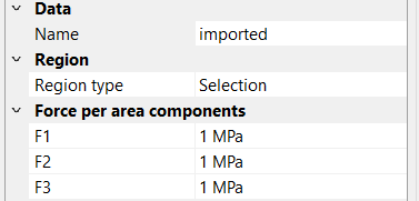
You can do this using the new Distribution feature in PrePoMax 2.4.0. It takes a text (ASCII) file in the following format (for vector used to define surface traction load) as an input:

X Y Z V1 V2 V3

where X,Y,Z are the coordinates of a point and V1,V2,V3 are the components of the (surface traction load) vector in force per unit area.

1 Like

The reason a force per unit area is used in PrePoMax is to enable mapping this field to another mesh. Using only forces, this is not possible.

1 Like

Thanks for your help.

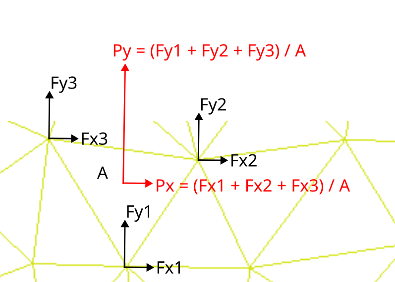
So, if I have the nodal forces, I need to compute the corresponding pressure components for each element, as shown in the figure. is that correct?

Then, I should create a .txt file containing the coordinates of the element centroids and the corresponding pressure components px, py, and pz (with pz = 0 in my case)?

Before posting here, I did some research on how to import a field distribution onto different meshes, and I found that interpolation can sometimes lead to unbalanced forces or momentum. What’s your opinion on that?

I had in mind to use the procedure of this paper to apply nodal forces on Calculix.

Thanks

The procedure you describe is accurate. You can export pressure values at element centres, and interpolation will map them to the PrePoMax mesh. But as you said, each interpolation introduces some error. The error decreases if the element sizes in both meshes are reduced.

if i can understand properly, it must follow tributary areas distribution concepts. Illustration figure missing an ‘..i’ to denotes individual element faces contribution e.g Fy3i, Fx3i, etc. Further calculation is needed to sum up all of neighbor element sharing common nodes, for example is Fy2i (1..7) since it has seven element face.

Hello,

I think your point is right if you have to transform element pressures to nodal forces. Vice versa, I believe it is the correct way. I have to check.

Thanks

Hello,

I have a few questions regarding load application in 2D analyses:

  1. Does this type of load work for 2D models? I tried it, but it doesn’t seem to behave as expected.

  2. If my pressure load acts only in the x–y plane, do I need to replicate the same forces at different z-coordinates?

  3. Can a distributed load extend beyond the domain boundaries?

Thank you for your help

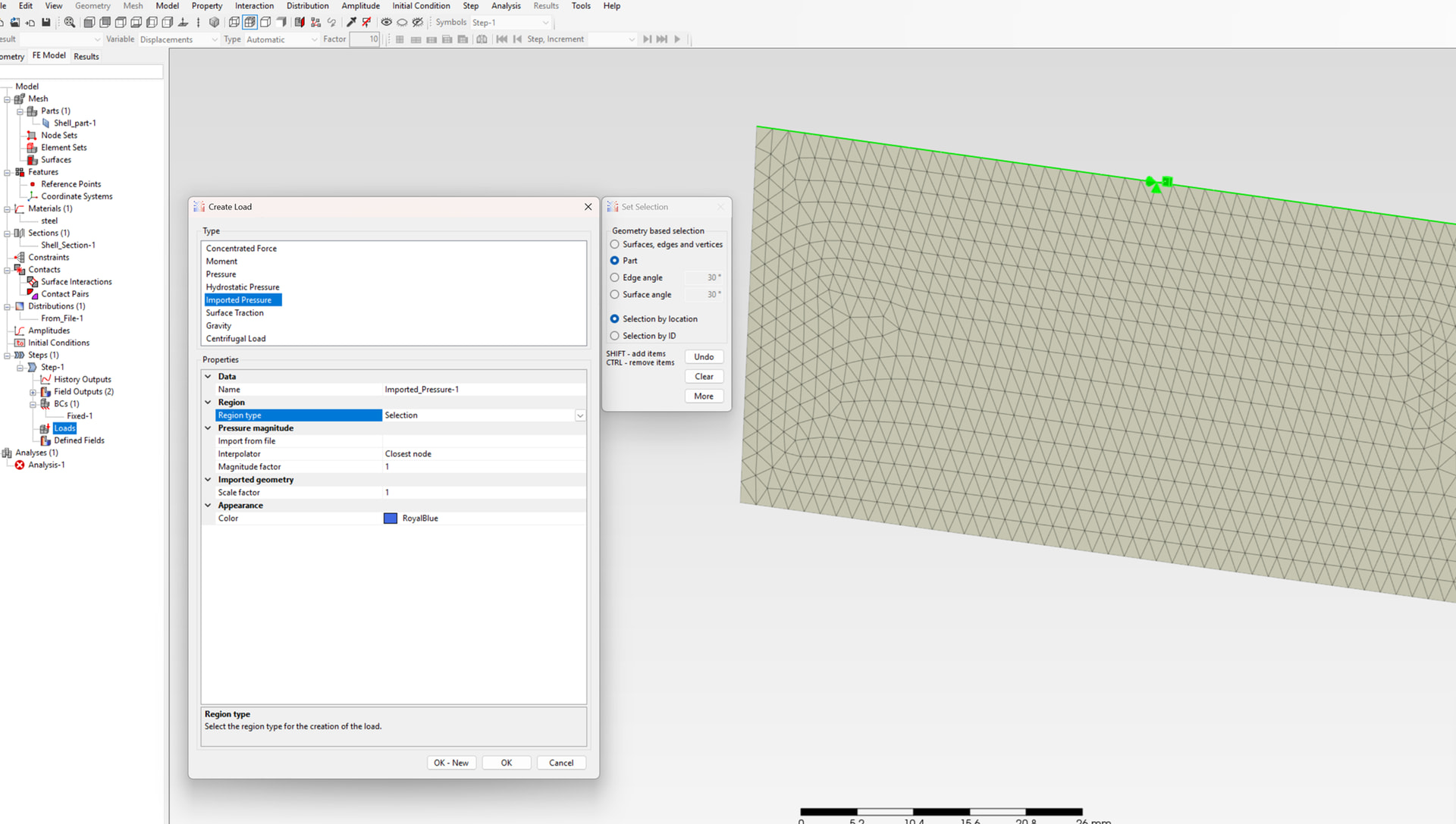
The Imported Pressure load that you show here is meant for use with OpenFOAM CFD analysis results. You should try regular Pressure or Surface Traction load with associated Distribution from file.

Gravity and centrifugal load accept my part while pressure and surface traction don’t.

You can’t select entire part for those kinds of loads, you have to pick surfaces (click on Selection and then directly on your geometry).

pressure and gravity loads let me select the edges and surfaces but if I use surface traction I can’t.

If you want to check I’ve attached my model.

test_2d.pmx (103.7 KB)

Thanks

It’s a plane stress model so you can’t apply such loads to faces - only to edges. Create a new model with Model Space set to 3D if you want to use shell elements instead and work in full 3D space.

Ok, it is clear.

Now, when I want to set the load, Prepomax still requires the pressure components. What values do I have to set if the load already define them?

To convert my 2d load to 3d load, I copied the same x-y element pressures for different z values so the file is like this:

x1 y1 z1 px1 py1 0

x2 y2 z1 px2 py2 0

x1 y1 z2 px1 py1 0

x2 y2 z2 px2 py2 0

test_3d_2.pmx (9.2 MB)

1 - it’s just a multiplier like for amplitudes defining time variation

1 Like

Hello,

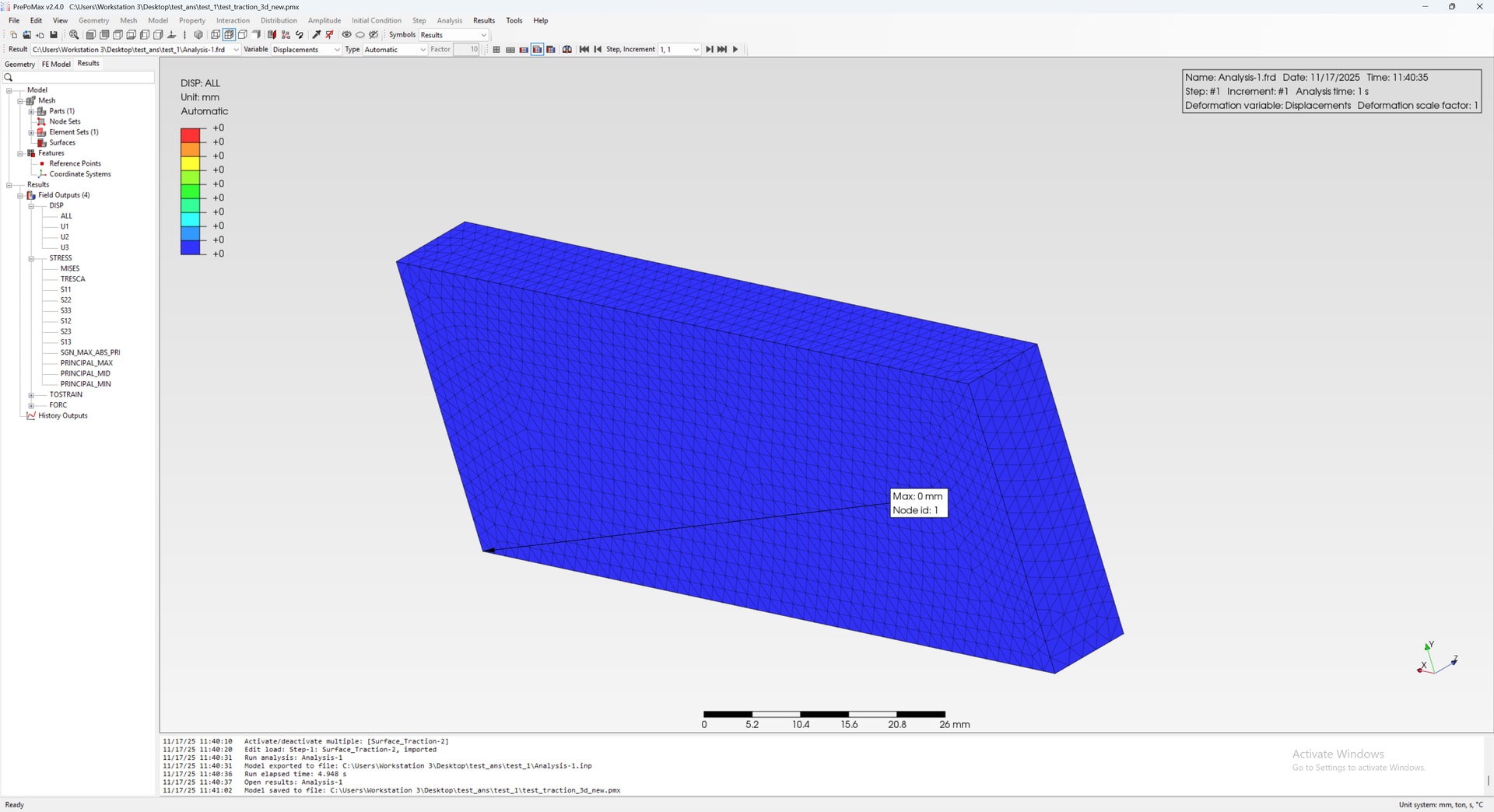
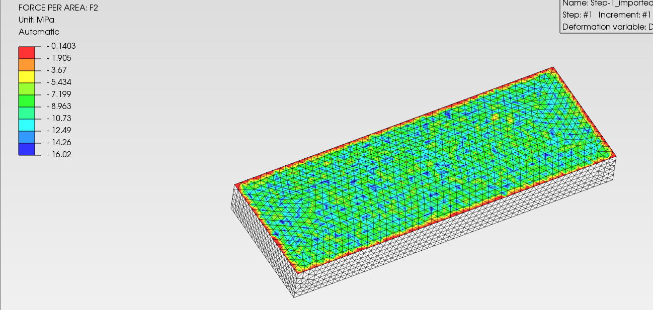
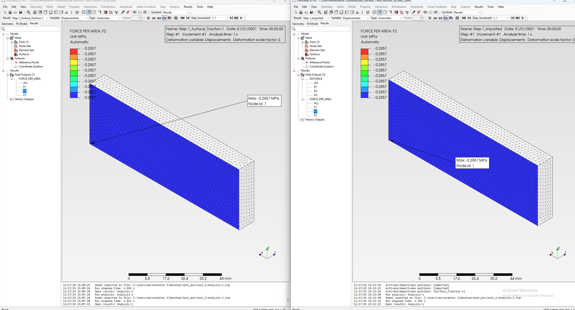
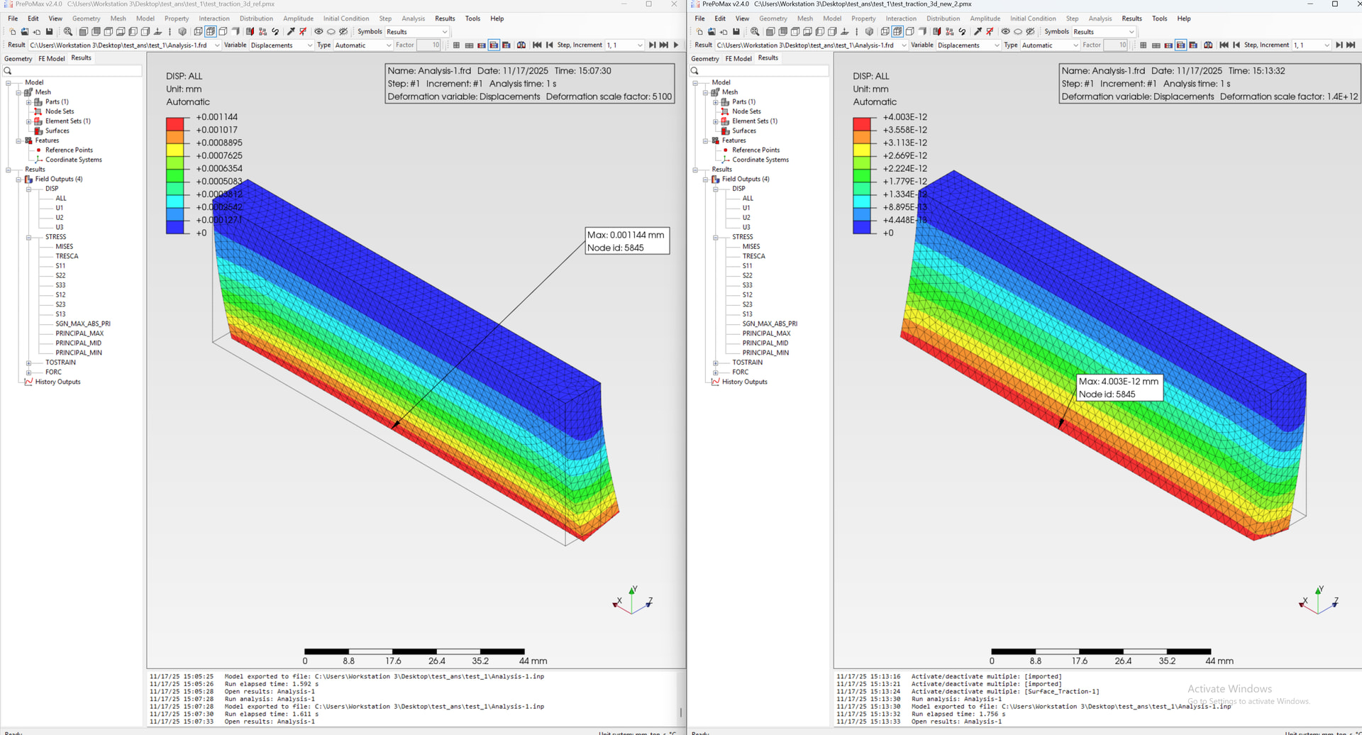
I am trying to compare the results of an imported distributed load on a surface with the PropoMax load, but I keep getting null results. The two loads should be equivalent. On my original mesh, I computed the force for each element using the following expression:
Fytot / Atot * area_el_j / Area_tot.
If there is an issue with the units or the values, I can correct that, but at the moment I am not getting any valid results to compare.

Could you please help me understand what might be wrong?

Thank you.

traction.zip (1.3 MB)

test_traction_3d_new.pmx (2.2 MB)

imported surface traction load

prepomax surface traction

Set 1 for the magnitude of all the components, then it should work.

Btw., you can right-click on the imported surface traction load and select Preview to see its distribution before running the analysis.

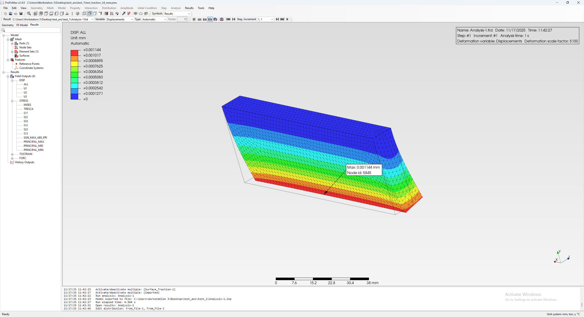
In fact, according to my simple tests with just two points (recommended before proceeding to full load definition), you may also have to set very small numbers (such as 1e-9) for the other components instead of setting them to actual zeros.

Thanks. With the fill value of 1e-9 I can finally obtain some results.
However, I still cannot understand how to make the two methods match.

To make the problem even simpler, I changed the load to a constant value equal to:

p = Ftot / Atot = 1000 / (0.0035e-6) = 0.2857 MPa.

Now the input file always contains the same py value, while the other load components remain equal to 1e-9.

To avoid interpolation errors, I selected the “closest” method.

The load preview looks correct in both cases, but the results still do not match.

This time I thought I would get identical numerical results and displacement plots, but this is not the case.

Does this comparison make sense? Or is it not possible to directly compare the two types of loads?

I apologize for the many questions, but I am evaluating the feasibility and reliability of the distributed load implementation for my future cases.

Thanks

traction.zip (763.1 KB)

There is definitely something wrong in terms of load size and direction. Let me check what is happening.

There is a bug that prevents the load from working correctly.

The comparison of the two loads is shown in the image below.

I have fixed it, but I will have to release a new version since there is no easy way around it. It will be done in the next few days.