Help Needed: Aircraft simulation in prepomax (Load ,Boundary Conditions, and Validation)

Hello,

I am new to PrePoMax and would really appreciate your help. I am trying to simulate an aircraft structure made of carbon fiber material with 2 mm thickness, and I have several questions:


1) Linear vs Nonlinear Simulation?
My aircraft model is hollow and approximately weighs 1700 kg. I want to know:

Should I perform the simulation using linear or nonlinear analysis to get more realistic and accurate results for such a lightweight yet large structure?


2) Load & Boundary Conditions Help
I’m facing trouble with the load setup and boundary conditions:

  • I applied Lift force upwards
  • I applied Gravity downwards
  • I fixed the bottom of the fuselage
    But I am confused about how to correctly apply Thrust and Drag forces.

What would be the correct way to represent them and where should I apply those boundary conditions?


3) How to Validate Simulation?
Once I run the simulation,

How can I validate the results?
Should I compare it with a handbook, physical tests, or another method?


Please guide me through this. I am doing this as part of my professional journey. Sometimes, a small tip from an experienced professional can save days of trial and error for someone just starting out. If you have any insights, resources, or suggestions, i’d truly appreciate your support - even a brief conversation would be incredibly helpful.

Thank you in advance for your time and Guidance!

Hi,
how much is your current element count?
Have you checked the element quality?

From your picture i would guess that a good coarse mesh will save you a lot of time until you find your final model setup.

1 Like

You can start from linear run, then add nonlinear features. It’s good to increase complexity gradually.

When it comes to loads, PrePoMax can use pressure from CFD so that could be the best way if you can set up and run OpenFOAM simulation: https://www.youtube.com/watch?v=76gqtkEhFwg

Regarding validation, just see if the results are reasonable (also check reaction forces), run a frequency analysis first to ensure proper connections between all parts and look for research papers covering similar subjects (possibly including experiments). But you could also start from a simple benchmark model with a known solution to verify your methodology itself.

1 Like

Thank you very much for your guidance.

I would like to share that I have already run the simulation under linear static conditions, but due to the very thin shell structure of the aircraft, significant buckling effects appeared. This is what led me to question whether a nonlinear approach might be more suitable.

As per your advice, I will now proceed with a frequency analysis first to verify the structural connectivity and setup. Regarding the pressure loading, I am coordinating with a colleague who is working on CFD simulations in OpenFOAM to extract realistic aerodynamic pressure data. Once available, I plan to use this data in PrePoMax for a more accurate representation of lift forces.

That said, I am facing some difficulties specifically with the application of boundary conditions. I would be grateful for your clarification on the following points:


1. Lift and Gravity Load Application

Currently, to apply lift (upward) and gravity (downward) forces, I am fixing the bottom surface of the fuselage as a boundary condition.
→ Is this an appropriate and realistic approach for restraining the model, or would you recommend a better alternative?


2. Wing Root Constraint Challenge

In typical simulations involving wing bending and torsion, the wing root (where it connects to the fuselage) is usually constrained. However, in my case, the entire aircraft is modeled as a single continuous shell body, without distinct connections or interfaces between the fuselage and wings.

→ Given that the model consists of one continuous body, how should I define the boundary conditions to appropriately simulate wing behavior?


3. Drag and Thrust Load Application

I also want to apply:

  • Drag force in the forward (longitudinal) direction
  • Thrust force in the rearward direction

→ In this context, what boundary conditions should I use to correctly apply these loads without causing rigid-body motion or instability?


4. Simultaneous Load Simulation

In reality, lift, gravity, drag, and thrust all act simultaneously on the aircraft.
→ Is it feasible to simulate all these loads together in a single static or nonlinear simulation step in PrePoMax?
If yes, what would be the appropriate boundary condition setup to simulate this realistically?


I hope this clearly explains my situation and questions. I truly appreciate your time and support in helping me progress through this structural simulation task.

At the moment, my model contains approximately 300,000 elements. I’ve used a relatively fine mesh to capture local behaviors, especially around curved areas and critical regions like the wing-fuselage interface.

However, I do understand your point — using a coarser mesh during the initial setup stages can help speed up the simulation and avoid unnecessary computational cost while debugging or tuning the model. I’ll try simplifying the mesh for initial runs.

Also, yes — I did perform an element quality check in PrePoMax and didn’t find any major issues like inverted or distorted elements, but I’ll double-check for any bad Jacobian or warped elements just to be sure.

I haven’t dug into the previous posts but I’ve some remarks:

  • your model can be probably simplified in order to be lighter
  • all grey areas let me thinking in high mesh density: as other people said, you can corser it
  • for the static simulations, you can take benefice of the symetry (1 dof blocked); no inertia relief in ccx so you’ve to find a way to block the 2 others)
  • well, concerning the symmetry, using shell elements is a nightmare for me when parts are curved (see also this post )
  • finally, a modal analysis must be performed on the full model, but you’re in free-free condition (but possible in ccx? otherwise another boundar condition difficulty using springs, etc)
1 Like

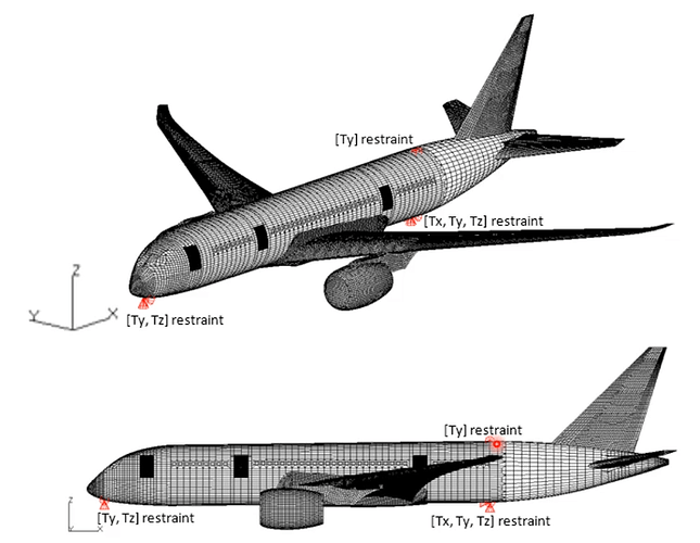
You could use the 3-2-1 method or soft springs to eliminate rigid body motions in this model. From D. Madier’s book:


Fig 11-19 Isostatic restraints on a full aircraft finite element model using the 3-2-1 rule

Check this post too: Basic Boundary Condition question - CalculiX (official versions are on www.calculix.de, the official GitHub repository is at https://github.com/Dhondtguido/CalculiX).

1 Like

As mentioned by others, you need a coarser model to debug and get going. After better understanding, then you can use finer meshes. You should target a fraction of your current element count.

How is that possible with carbon fiber? The max takeoff weight of a Cessna 172 is ~ 1100 kg. I haven’t done the math, but a hollow 2mm thick carbon fiber model, should not be 1700kg. Check your math.

I think you are starting backwards, you should pick something you know from handbooks, physical tests, or even analytical calculations. Then build your model with that in mind.

Here are my 2p on your questions:

  • I think that you need to go back to pen and paper and draw a rigid body diagram with forces you want to apply, and possible reactions on constraints. If the net sum per DoF do not add up to zero ==> it is not statics as is, and something else is required to make it quasi-static.
  • Study and understand the 3-point constraint method you’ve been given above, it is a general method, not just for airplanes. It also allows for thermal loads (contract/expand) while avoiding over-constraints.
  • follow the suggestions of a tiny model 1st, model a cross in CAD or similar and make it tiny in terms of the node count. Then check if your method balances the input loads and sum of reactions at the 3-point method locations; and that no artificial constraint is introduced.
  • once you have s’thing that makes sense as a method with the tiny ‘cross’ dummy CAD ===> try on the airplane model.
  • Nothing is fully rigid in real life, it all distorts/moves even if it is microns, and that can matter, and more so on an airplane, do not constrain any faces in any DoF, it’ll be wrong. Understand the 3-point constraint method.
  • Also do not forget to do 1st hand calcs on pressure loads and areas you are modelling, do they really make sense, is the assy mass/inertias about right from CAD? This is the rigid body sketch on a bit of paper.
  • Once you’ve done all that, ask again if still not sure.
1 Like

I agree 100% with this.