Hello, I’m new to PrePoMax and I’m trying to create a strength analysis on this structure. Supporting structures and the cylinder is shell while the surface beneath the cylinder (deck) is a solid with 16mm of thickness. Meshing parameters are applied to all parts (250mm max, 25mm min), local mesh is applied to those little holes for bolts (both to flange and solid), shell gmsh is applied to cylinder and supporting structures and lastly I used extrude mesh for solid (to be able to create quad meshes). After meshing the structure, holes on the solid just dissapears as if they were not even there in the beginning (they are perfectly fine on the flange of the cylinder). Deactivating the extrude mesh solves the problem but that solid part needs to have quad meshes, it’s a must. By going advanced and choosing quad meshes to on in the meshing parameters unfortunately doesn’t create quad meshes on the solid structure. What should I do? Thanks in advance.

Apparently, you’ve encountered this issue where Extrude works for geometries not valid for this algorithm (only the ones that can be simply extruded from one side in one direction without changes along the way are applicable): Why does the holes closes in "FE MESH"?
It should be fixed in the next release.
If you need hexahedral elements for the solid part and it’s thin-walled, you can try Shell Gmsh + Thicken Shell Mesh. However, if it’s not thin-walled/hollow, you will likely have to split it into subvolumes with 5/6 faces (having 3/4 edges each) and use Transfinite algorithm if you really need a hex mesh and there are holes on the side. Or split it into parts that can be extruded separately and then connected with tie constraints.
Thanks for the reply, I will definitely try that. Also when I create this structure all with shells (deck + supporting structures are a whole 1 compound and cylinder+flange+endplate is a one compound), even though PrePoMax finds a surface contact between flange and the deck when I apply a force to the cylinder flange phases through the deck like if there is no surface contact between them. It was also happening when I was trying the analysis with deck and supporting structures were different 2 compounds. Does PrePoMax have a problem with shell-shell constraints/contacts?
Make sure that you view the results with deformation set to true scale (1). Contact should work for shells as well. You need properly refined meshes, though (make sure master has a coarser mesh).
Thanks for the feedback, I ran the analysis with full shell structure but it kept going for more than 30 minutes so I terminated it assuming there is a problem (Probably getting further away from the solution with every equation rather than getting closer). I can’t attach any files due to my account being so fresh. Is there a way for me to send you the PrePoMax file if it’s possible for you to check it out? Thanks in advance.
Did you try with tied contact or tie constraints ?
Regarding the file sharing, there are a few ways including also various hosting services. I sent you a pm with the details.
Is it possible to share the model for testing? I am interested in the solid model where the geometry is altered after meshing.
Sure, you can find it in the attached files. Though I ran the analysis with full shell and it works fine at the moment thanks to FEAnalyst. I would still be interested to hear your feedback though. Best regards.
FINAL-SOLID.pmx (2.1 MB)
The problem was just making the extrusion from the side so it ignored the holes:

Doing it from the bottom/top works.
Here’s the file reduced to this solid part:
FINAL-SOLID mod.pmx (872.1 KB)
Thanks for the feedback, when I tried top to bottom it took forever to generate meshes and it crashed eventually. Is there a thing to make this work?
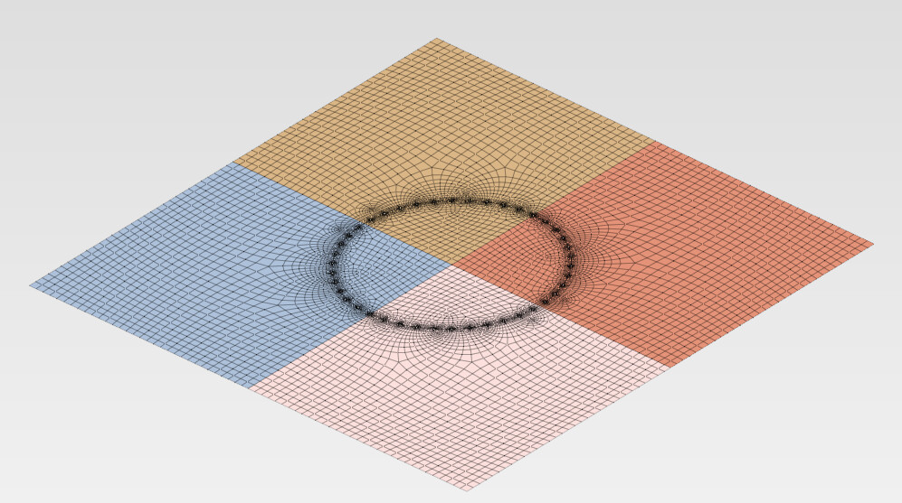
I worked it out but it doesn’t create smooth meshes like from the side, it looks like a “cob web” and so dense
Try different recombination algorithms or Sweep (instead of Extrude) because it supports the Quasi-structured quad algorithm (the most regular one). Start from a coarser mesh, then refine if needed.

Thank you for the file. In the new version (2.5.2), additional checks were added to the side surfaces of the extruded domains. I tested it on this geometry, and meshing from the side is no longer allowed.
Hi,
My idea is to export the sheet metal to FreeCAD, divide it with one sketch, and import it to PrePoMax.


Yes, partitioning (also using transverse planes) should improve the mesh quality here. Perhaps also symmetry could be utilized.
With some more divisions using Slice apart with datum planes for the symmetry cuts and then Boolean fragments for the face partitions:


Of course, it’s possible to mirror and merge the coincident nodes it later if the whole plate is needed:

Dear @Matej
Where can we download ver. 2.5.2 ?
It’s not yet released. You would have to compile yourself.
It will be released in a couple of weeks.