Compression Only & Surface Spring Validation file

Hi,

I have thought the simplest validation I would be able to solve by hand in order to understand better and compare side by side the Compression Only Support with the Surface Spring Support.

Attached is my proposal. The agreement is perfect as far as I have checked with some comments.

It could be the base to do some comments and further tests. I also think this understanding can be useful to define better the initial values for the Only compression Support.

File attached and the hand calculation. I hope it is understandable. It’s basically a balance.

Comments.

  • Tested with traction, gravity, and pressure.

  • It has puzzled to me the way Surface Stiffness N/mm3 relates with linear Stiffness N/mm.
    To be equivalent, user should remember Surface Stiffness [N/mm3 or better read MPa/mm] * Surface [mm2]= Linear Stiffens [N/mm].
    In my example the Overall surface where the Surface Stiffness is applied is 10000000 mm (10mx1m) base.That is the conversion factor

  • @Matej - Contrary to what I understood, Linear stiffness [N/mm] takes the contributive area of each node into consideration. That’s what the results show.
    I have substituted the Only Compression support by too springs and the results by hand and it is the same. Also included in the file (deactivated)

  • Surface Spring assumes the surface is always attached to the springs and the springs work in both directions , compression, and traction if there is Uplift. (T) in my hand-calculations.

  • Further refinement has been done to see the evolution. The supported area has more nodes and the support is more uniformly distributed.

  • I don’t think elastic Foundation and shells is a good idea. Shells (don’t work) and I can’t remove nodal average to check reactions.

  • Reactions at the support and springs can also be checked (Solid).

@Matej -I can’t figure out what is the exact role of the Tensile force in the Compression Only window.?¿?¿

Elastic Supports

Yes - surface spring assumes a single spring with stiffness in N/mm is attached to the surface. Then it distributes its stiffness to the nodes. The same as surface traction does with the force.

I have fixed the behavior in the shells. I did not release the code jet. It will be version 1.5.6.

The gap elements are used in compression only support. They are defined by two parameters to describe the shape of the displacement - force diagram (CalculiX documentation).

1 Like

Manual says :

• spring stiffness (default 1012 [force]/[length])
• tensile force at −∞ (default 10−3 [force])

They have different units . That tensile force at -infinite can’t be the constant value shown in the graph.

The figure is for contact parameters where displacement vs pressure is shown. For gap elements, one must replace the pressure with force. The constant value is the force - as far as I understand. So, moving the component in the direction away from the compression-only support should not increase the force of the compression-only constraint.

Thank you.
Do you know if this value is per spring or is it distributed for the whole set.?

In CalculiX, it is per gap element. In PrePoMax, the entered value is per surface selected - it is then accordingly distributed to all gap elements.

1 Like

Hi Matej,
Shells still show 1/2 the expected compressive stress S33. Is the nodal average issue pending for future versions? Just wanted to confirm you are aware of the issue.


First, I tested an example with solid and shell mesh in bending to see if the pressure direction was correctly implemented. Fixed support and pressure only.

Model

Displacement

Mises

Then, I added a step and changed the model to compression. I changed the supports only. I was careful not to over-constrain the model. The results make no sense. The solid is in compression as it should be, while the shell is in tension. And the stress is 0.5 of the expected stress. And I only used normal supports.

So, I don’t think the compression-only elements are to blame.

Model

Displacements

Mises
SGN-MAX-ABS-PRI

solid_shell.pmx (90.0 KB)

as i know PrePoMax only read FRD file output from CalculiX even some stress output like Mses is not. So, t’'s probably related to the solver in shell element implementation.

If shell stress is written to the .dat file the result is the same as in .frd file. For some reason, the .dat file from the shell elements cannot be read into PrePoMax.

Is seems the difference is that in the .dat file the S33 stress is the stress in the shell thickness direction no matter the global system.

I fixed the .dat reader to support reading the shell stresses.

Thank you Matej.
Did that fix the ss3 value?

Well, no. The values are the same as in .frd file only the axes are switched.

Hi Matej,

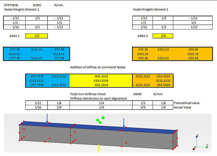
I have extended my hand calculation on the simple balance to parabolic HEX elements.
It just implies adding more terms to the equation of sum of moments = 0.

Analytical solution for reference:

-Surface Spring Support Maximum U3 = -8.88mm
-Compression Only Support Maximum U3 = -10.0mmmm

Noticed that this is the solution for a balance with discrete supporting points. It doesn’t have mesh refinement error associated.
This result agrees with the values obtained on a first refinement using Linear elements. Can be seen on the second line of my table above (4 C3D8)

Prepomax don’t agree with the expected values when using Parabolic Hex Elements.

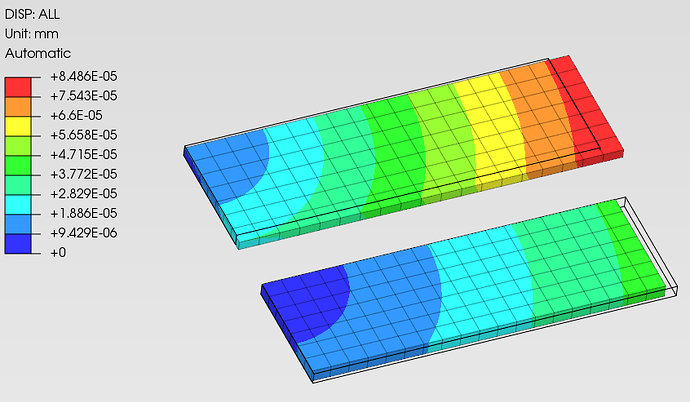
Figure shows from left to right. (Expected Surface Spring , Surface Spring implemented, Expected Compression Only, Compression Only implemented)

Before starting with speculations about the source of this discrepancy I would like to ask you something.

-Does Prepomax create a spring on each node or do you just create springs on midsize nodes (Those with positive weight according to Figure 153)?

-In case you are just using some of the nodes , ¿do you distribute the stiffness associated to the nodes that are not used so we do not loose overall Stiffness?

Thanks in advance.

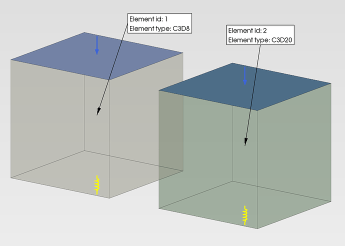
maybe it can start by single element to understand clearly regarding surface spring and traction implemented in PrePoMax.

validation and verification of linear spring can take from external reference such as textbook or paper, this can be review for both linear and quadratic element also.

in case compression-only by gap element, it’s actually simplification problem of elastic contact. Comparable with full model (two part) with penalty contact or tied contact with stiffness overrides.

**
** Heading +++++++++++++++++++++++++++++++++++++++++++++++++
**
*Heading
Hash: uyOtHNO2, Date: 11/27/2023, Unit system: MM_TON_S_C
**
** Nodes +++++++++++++++++++++++++++++++++++++++++++++++++++
**
*Node
1, 0.00000000E+000, 1.00000000E+000, 0.00000000E+000
2, 0.00000000E+000, 0.00000000E+000, 0.00000000E+000
3, 1.00000000E+000, 1.00000000E+000, 0.00000000E+000
4, 1.00000000E+000, 0.00000000E+000, 0.00000000E+000
5, 0.00000000E+000, 1.00000000E+000, 5.00000000E-001
6, 0.00000000E+000, 0.00000000E+000, 5.00000000E-001
7, 1.00000000E+000, 0.00000000E+000, 5.00000000E-001
8, 1.00000000E+000, 1.00000000E+000, 5.00000000E-001
9, 0.00000000E+000, 5.00000000E-001, 0.00000000E+000
10, 5.00000000E-001, 1.00000000E+000, 0.00000000E+000
11, 1.00000000E+000, 5.00000000E-001, 0.00000000E+000
12, 5.00000000E-001, 0.00000000E+000, 0.00000000E+000
13, 0.00000000E+000, 5.00000000E-001, 5.00000000E-001
14, 5.00000000E-001, 0.00000000E+000, 5.00000000E-001
15, 1.00000000E+000, 5.00000000E-001, 5.00000000E-001
16, 5.00000000E-001, 1.00000000E+000, 5.00000000E-001
17, 1.00000000E+000, 0.00000000E+000, 2.50000000E-001
18, 0.00000000E+000, 0.00000000E+000, 2.50000000E-001
19, 1.00000000E+000, 1.00000000E+000, 2.50000000E-001
20, 0.00000000E+000, 1.00000000E+000, 2.50000000E-001
**
** Elements ++++++++++++++++++++++++++++++++++++++++++++++++
**
*Element, Type=C3D20, Elset=Solid_part-1
1, 1, 2, 4, 3, 5, 6, 7, 8, 9, 12, 11, 10, 13, 14, 15,
16, 20, 18, 17, 19
*Element, Type=SPRING1, Elset=Surface_Spring-1_All
2, 1
3, 2
4, 4
5, 3
6, 9
7, 12
8, 11
9, 10
**
** Node sets +++++++++++++++++++++++++++++++++++++++++++++++
**
*Nset, Nset=Internal-1_Internal_Selection-1_Surface_Spring-1_Master
1, 2, 3, 4, 9, 10, 11, 12
*Nset, Nset=Internal-1_Internal_Selection-1_Surface_Traction-1
5, 6, 7, 8, 13, 14, 15, 16
*Nset, Nset=Internal_Selection-1_Displacement_Rotation-1
5
**
** Element sets ++++++++++++++++++++++++++++++++++++++++++++
**
*Elset, Elset=Internal-1_Internal_Selection-1_Surface_Spring-1_Master_S1
1
*Elset, Elset=Internal-1_Internal_Selection-1_Surface_Traction-1_S2
1
*Elset, Elset=Surface_Spring-1_1_DOF_3
2
*Elset, Elset=Surface_Spring-1_2_DOF_3
3
*Elset, Elset=Surface_Spring-1_4_DOF_3
4
*Elset, Elset=Surface_Spring-1_3_DOF_3
5
*Elset, Elset=Surface_Spring-1_9_DOF_3
6
*Elset, Elset=Surface_Spring-1_12_DOF_3
7
*Elset, Elset=Surface_Spring-1_11_DOF_3
8
*Elset, Elset=Surface_Spring-1_10_DOF_3
9
**
** Surfaces ++++++++++++++++++++++++++++++++++++++++++++++++
**
*Surface, Name=Internal_Selection-1_Surface_Spring-1_Master, Type=Element
Internal-1_Internal_Selection-1_Surface_Spring-1_Master_S1, S1
*Surface, Name=Internal_Selection-1_Surface_Traction-1, Type=Element
Internal-1_Internal_Selection-1_Surface_Traction-1_S2, S2
**
** Physical constants ++++++++++++++++++++++++++++++++++++++
**
**
** Materials +++++++++++++++++++++++++++++++++++++++++++++++
**
*Material, Name=S235
*Density
7.8E-09
*Elastic
210000, 0.28
*Expansion, Zero=20
1.1E-05
*Conductivity
14
*Specific heat
440000000
**
** Sections ++++++++++++++++++++++++++++++++++++++++++++++++
**
*Solid section, Elset=Solid_part-1, Material=S235
*Spring, Elset=Surface_Spring-1_1_DOF_3
3
-8.33333333E+001
*Spring, Elset=Surface_Spring-1_2_DOF_3
3
-8.33333333E+001
*Spring, Elset=Surface_Spring-1_4_DOF_3
3
-8.33333333E+001
*Spring, Elset=Surface_Spring-1_3_DOF_3
3
-8.33333333E+001
*Spring, Elset=Surface_Spring-1_9_DOF_3
3
333.333333333333
*Spring, Elset=Surface_Spring-1_12_DOF_3
3
333.333333333333
*Spring, Elset=Surface_Spring-1_11_DOF_3
3
333.333333333333
*Spring, Elset=Surface_Spring-1_10_DOF_3
3
333.333333333333
**
** Pre-tension sections ++++++++++++++++++++++++++++++++++++
**
**
** Constraints +++++++++++++++++++++++++++++++++++++++++++++
**
**
** Surface interactions ++++++++++++++++++++++++++++++++++++
**
**
** Contact pairs +++++++++++++++++++++++++++++++++++++++++++
**
**
** Amplitudes ++++++++++++++++++++++++++++++++++++++++++++++
**
**
** Initial conditions ++++++++++++++++++++++++++++++++++++++
**
**
** Steps +++++++++++++++++++++++++++++++++++++++++++++++++++
**
**
** Step-1 ++++++++++++++++++++++++++++++++++++++++++++++++++
**
*Step
*Static
**
** Output frequency ++++++++++++++++++++++++++++++++++++++++
**
*Output, Frequency=1
**
** Boundary conditions +++++++++++++++++++++++++++++++++++++
**
*Boundary, op=New
** Name: Displacement_Rotation-1
*Boundary
Internal_Selection-1_Displacement_Rotation-1, 1, 1, 0
Internal_Selection-1_Displacement_Rotation-1, 2, 2, 0
**
** Loads +++++++++++++++++++++++++++++++++++++++++++++++++++
**
*Cload, op=New
*Dload, op=New
** Name: Surface_Traction-1
*Cload
5, 3, 83.3333333333333
8, 3, 83.3333333333333
7, 3, 83.3333333333333
6, 3, 83.3333333333333
16, 3, -3.33333333E+002
15, 3, -3.33333333E+002
14, 3, -3.33333333E+002
13, 3, -3.33333333E+002
**
** Defined fields ++++++++++++++++++++++++++++++++++++++++++
**
**
** History outputs +++++++++++++++++++++++++++++++++++++++++
**
**
** Field outputs +++++++++++++++++++++++++++++++++++++++++++
**
*Node file
RF, U
*El file
S, E, NOE
**
** End step ++++++++++++++++++++++++++++++++++++++++++++++++
**
*End step

When using a point spring the spring is only created in the selected nodes. And the same stiffness is applied to all spring elements. No change in the entered spring stiffness happens.

When using a surface spring, the stiffness is redistributed to all nodes accounting for the nodal weights. The springs are added for all nodes where the model weight is not equal to 0. For nodes with 0 nodal weight, no spring is added. For nodes with negative nodal weights, the spring stiffness is negative.

If a uniform load is applied, a uniform stress field should appear in the element. Using the description above creates a uniform stress field under a uniform load. I did not test other cases.

Thank you Matej.

I’m updating my validation file for parabolic elements according to your comments to see what I get. Imposing a uniform stress field under a uniform load seems a restrictive condition.

If that is how Surface spring is defined it might be the source of discrepancy as I have not enforced that condition. Probably with refinement and large stiffness both deliver the same result but with coarse meshes the behavior is different to mine.

Thanks again.

My idea was that a surface spring support should enable the simulation of a constant stress field. So when using a single hex element and applying a pressure condition to the top of the element and a surface spring support to the bottom of the element one would get a constant stress.

Model

Displacement

Stress

File:
One_hex.pmx (22.7 KB)

Much clear now. My hand calculation wasn’t considering that imposing uniform Stress under uniform load in parabolic elements requires additional weights on top of participating area .
Minus sign makes it even more tricky.
Thanks again.

some disadvantages, Nlgeom deactivated in Gap element lead to soften the spring stiffness by half. It’s not used initial value as linear spring to be meaning in results and the purpose of preliminary analysis.

hopefully, the solver code of CalculiX made changes to do improvement in the future.