I’m currently experimenting with the new distribution option “from equation” to rotate a bearing load based on an angle input using parameter (a), which always acts on one half of the bearing surface. This works if I partition the lateral surface according to the angle and apply the force only to this area (180° segment).
However, it would be ideal to be able to directly select the entire lateral surface without prior partitioning and to define the orientation of the half-surface areas directly based on the angle input (a). So my question is, does anyone know a trick that would allow the force to be automatically set to zero on the opposite 180° surface?
Yes Matej, you mentioned it before, but I don’t know exactly how to apply it
This picture shows what i am doing so far (selecting one half of the splitted surface). If you can, would you please give me a concrete hint to complete the equation for the full 360° surface selection? I would be very grateful
I use parabolic distribution to apply bearing load. Considering z vertical and x transversal (y parallel to the hole axis) the equations that I had implemented for Mecway and last week for Prepomax, are the following:
X-components
cosθpmax(xcosθ-zsinθ)/RPow((Cos(π/aAcos((xsinθ+zcosθ)/R))),2) - x component
-sinθpmax(xcosθ-zsinθ)/RPow((Cos(π/aAcos((xsinθ+zcosθ)/R))),2) - z component
Z-components
sinθpmax(xsinθ+zcosθ)/RPow((Cos(π/aAcos((xsinθ+zcosθ)/R))),2) - x component
cosθpmax(xsinθ+zcosθ)/RPow((Cos(π/aAcos((xsinθ+zcosθ)/R))),2) - z component
Where:
θ is the angle between z axis and force direction (θ is positive counter clockwise on plane x-z)
pmax is the peak value of the pressure:
a is the pseudo-angle of contact (for example, on the equations, π/a =3 for a=60° (π/3)
D is the hole diameter
R = D/2
b is the plate thickness
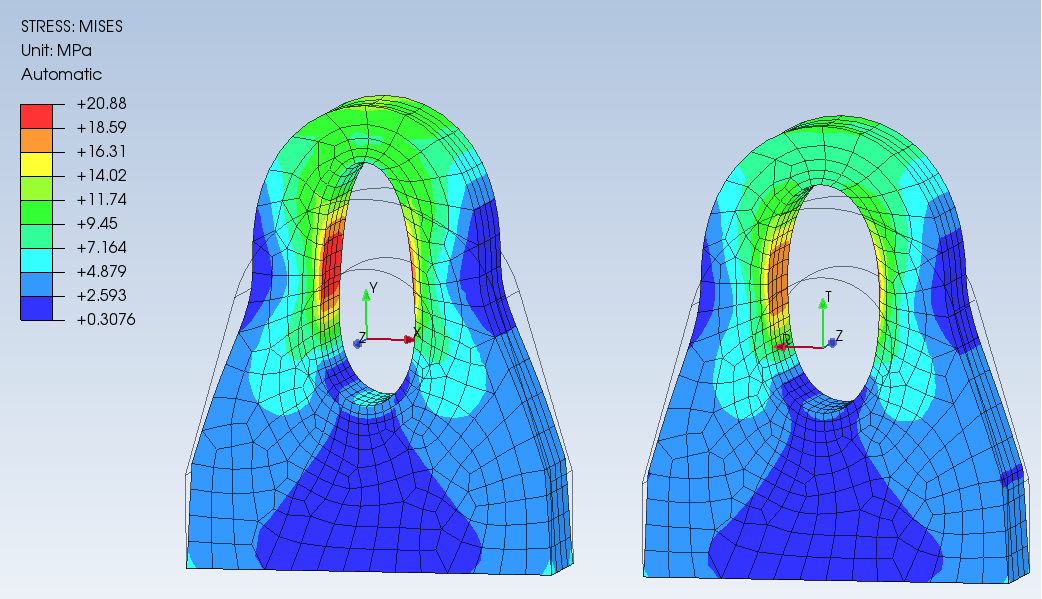
I attach an example with hole center placed on x=0 and z=0, F=75 kN, θ=-30° acting on 60° portion. The equations could be translated on hole center placed on arbitrary point on x-z plane (y=0) Padeye-inclined-1.pmx (2.2 MB)
Yes, are based on global cartesian coordinate. The problem for me is also what kind of distribution is better. It depends above all from tolerance between male (pin or rolling bearing) and female (hole). I work with shackle and padeye and parabolic distribution over an angle less than 90°is not real but more realistic. Generally, to fit a shakle pin on a padeye the hole diameter should be at least 2-3 mm more tha nominal shackle pin diameter. For DNV clearance between shackle pin and padeye hole shall not exceed 6% of the shackle pin diameter.
For example WLL12t shackle Øpin=35 mm Øhole=37mm
On this kind (parabolic) of distribution only experience (many times I observed ovalized hole due to excessive clearance or local excessive bearing stress)
Other considerations are derived from some FEA analysis with contact.
I know that for roller bearing fitting Gencoz distribution that seems to be more real. But we are speaking of IT6/7 (index of tolerance)
Only the halve of the hole, where the y-vector is positive (expression x* sin(a_rad)+y* cos(a_rad)), the load distribution is not zero! This allows the entire surface to be selected without having to split it!
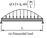
I just extended this sinusoidal load function with the rotation matrix. Since I replace L with the diameter, the distribution always acts on the half circumference.
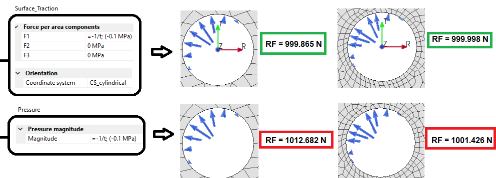
So in this case it works only with pressure loads, which would not be my preferred choice since the resulting reaction force seems to be more mesh dependend.
In general, there is always a possibility to convert from one coordinate system to another mathematically, but it gets impractical.
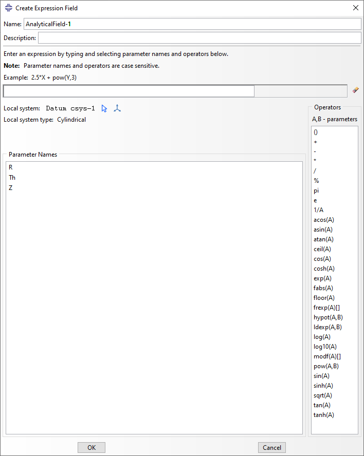
So I see the support for a local coordinate system will be beneficial? Currently, x, y, and z symbols are reserved for parameter names in equation-based distributions in the entire PrePoMax. Even in the creation of user-defined parameters, these symbols cannot be used. If I support local coordinate systems, should I stay with x, y, and z or use a more general x1, x2, and x3? Remember, selected symbols are reserved for equation-defined fields.
But generalized axis names would also make sense. Probably x,y,z will be good enough since we assume rectangular coordinates as default and x1,x2,x3 can be less intuitive in this case.
A bearing load can also be simulated by a sine distribution. So if you define a cylindrical coordinate system on the axis of the hole with the z axis aligned with the hole axis and the r axis aligned with the radial direction the distribution can be defined simply by:
=sin(y)
If the hole is not split into two halves, you can add an if statement to limit the starting and end angles as:
=if(y > 0 && y < Pi; sin(y); 0)
At the end, you should compute the scaling factor (or measure the reaction force) to get the desired load.