Good afternoon to all
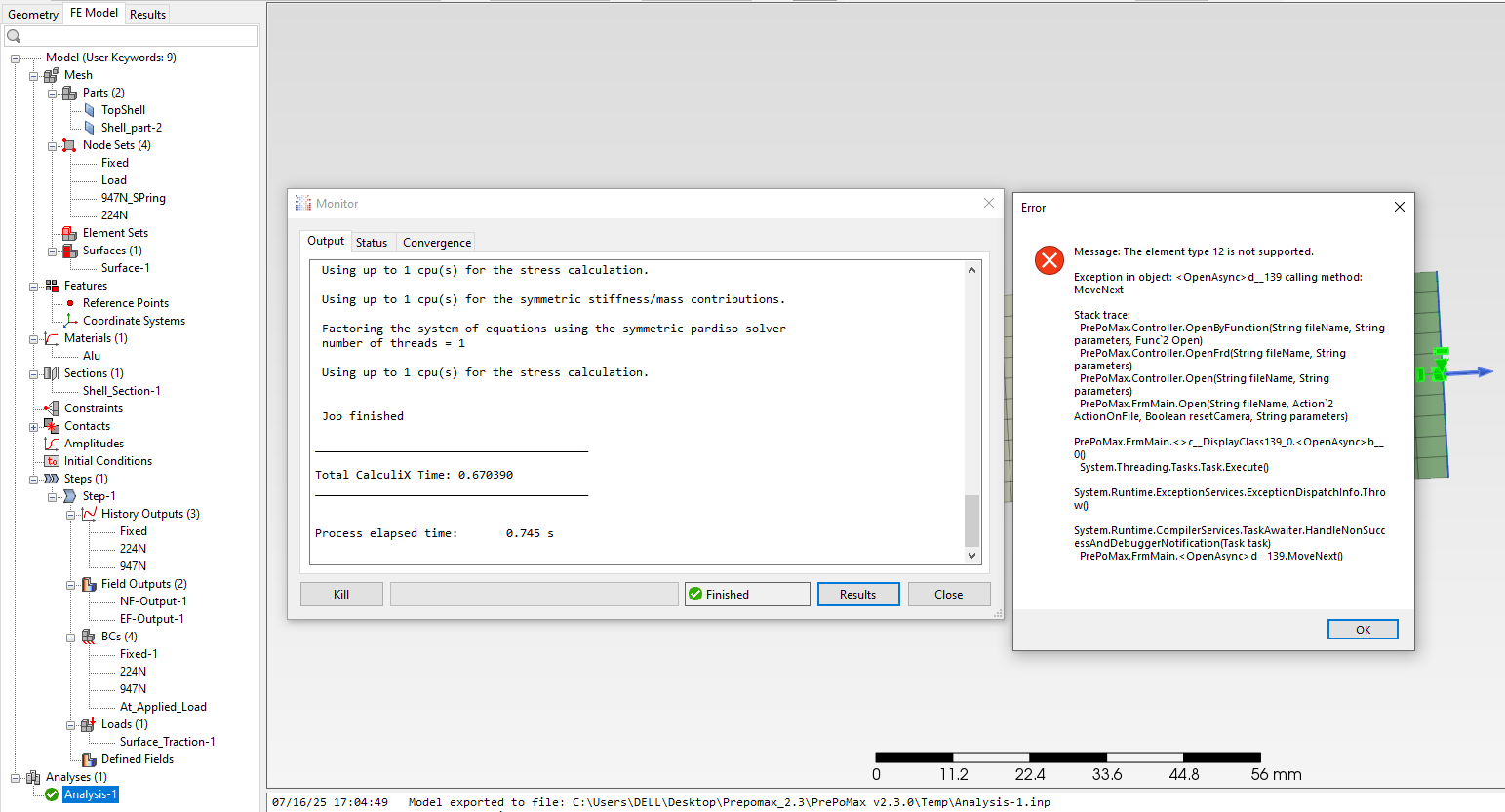
If any one can help me to create (circular beam elements in between two plates ). I am Struggling to get output results . i got this type of error as show in the pictures . Explain where i made mistake .


Thanks …
Good afternoon to all
If any one can help me to create (circular beam elements in between two plates ). I am Struggling to get output results . i got this type of error as show in the pictures . Explain where i made mistake .
Thanks …
Can you share the .pmx file ?
Circular beam section requires second-order beam elements. But it may still fail so I replaced shells with extruded solids, CalculiX often has issues with 1D and 2D elements.
Bolt_beam_works.pmx (350.7 KB)
Thanks Sir ,
Is their Any possibility of replacing beams with springs .Like this
Bolt-Analysis (with Spring).pmx (382.4 KB)
Yes, springs may also make sense but keep in mind CalculiX’s limitations and everything we talked about in this thread: Why the top plate displacement is zero?
Thanks sir ,
Now I run the 2D plates with rectangular beams in between two plates .but the rectangles are not connected in between two plates . can any one find where i do mistake and correct it .i am also attached my preprmax file .
Bolt_beam_works (2D)(with results ).pmx (401.4 KB)
They are connected and deform:
This image is from a frequency analysis that you should run to check the connection.
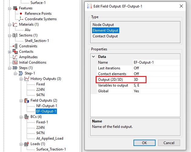
It’s the 3D beam section rendering making it appear wrong. You can disable it by switching to 2D output here:
Thanks a lot sir ,
In this Fe analysis results i donot know why the center beam has more stress as compared with other stresses at remaining two beams . can any one explain it in detail . from my calculations says that first and last fasteners are going to pick more load as compare with middle fastener . here i attached pmx file and calculations
Bolt_beam_works (2D)(with results ).pmx (232.5 KB)
HI,
In my experience the comparison between FEA and values suggested by different sources differ slightly.
I agree middle rivets absorb less load but it’s percentual values depends on the BC, how the rivets are modeled and their stiffness ratio to the plate stiffness.
As an example, using springs and three rivets , I have found load distributions that can vary from 34.5%/30.9% to 33.6%/32.8%.
Airframe-Stuctural-Design report up to 40%/20% and the difference dilute as the springs become softer.
Kinematic couplings between the two surfaces (no beams or springs) deliver closer values to the 40%/20%/40% like 45%/12%/43%
In my opinion Prepomax is still not ready to do such comparisions in a fluent manner. I would wait to see if Matej could implement Springs and beam elements.
Regards
Values in recent studies also suggest the is no such difference (40/20/40) in between extreme and middle rivets.
Take a look at this paper.
when bolts are subjected to shear, spring stiffness should be using shear modulus as base instead of elastic modulus, also an effective shear area need to consider instead of gross section as previously shown.
regarding to stress distribution of individual bolt, it seems solid element can give some insight to represent actual behavior since many parameters may affect. Spring and beam model can loss in accuracy due to some degree of fixation at bolt head or nut during transferring shear forces.
the graph is ratio of plate to rivet spring constants as denoted by closed brackets, not the stiffness of bolt or rivet itself.
I’m comparing load distribution for different ratios between plate and rivet constants.
The stiffness base for comparison shown in the chart is always the same. K=AE/l. It is related to the plate properties, and it is computed using E not G no matter the rivet geometry or load configuration.
did it mean a proposed of bolt/rivet spring value based on ratio to plate stiffness? i don’t think so.
As previously shown,
Where?. Looks like you are correcting something previously shown that wasn’t right.
probably the calculation of K for stiffness and illustration figures are mismatch, i’m not in detail about reasonably value shown, only in units and variable.
also, i did not understand why too much concern in plate stiffness instead of bolt/rivet itself in proposed to be implement in PrePoMax.
p.s i’ve been trying different approach of bolt model in CalculiX, hardest part is representing degree of rotational fixity at bolt ends and cumbersome tasks defining of each element orientation.
“Hi, I am facing a problem in PrePoMax while connecting two plates with two springs and one circular beam. It runs correctly, but after running, it shows an error. Can anyone explain where I made a mistake?”
I got this error …Prepomax file also attached below
One Rivet in between two plates_01.pmx (354.4 KB)