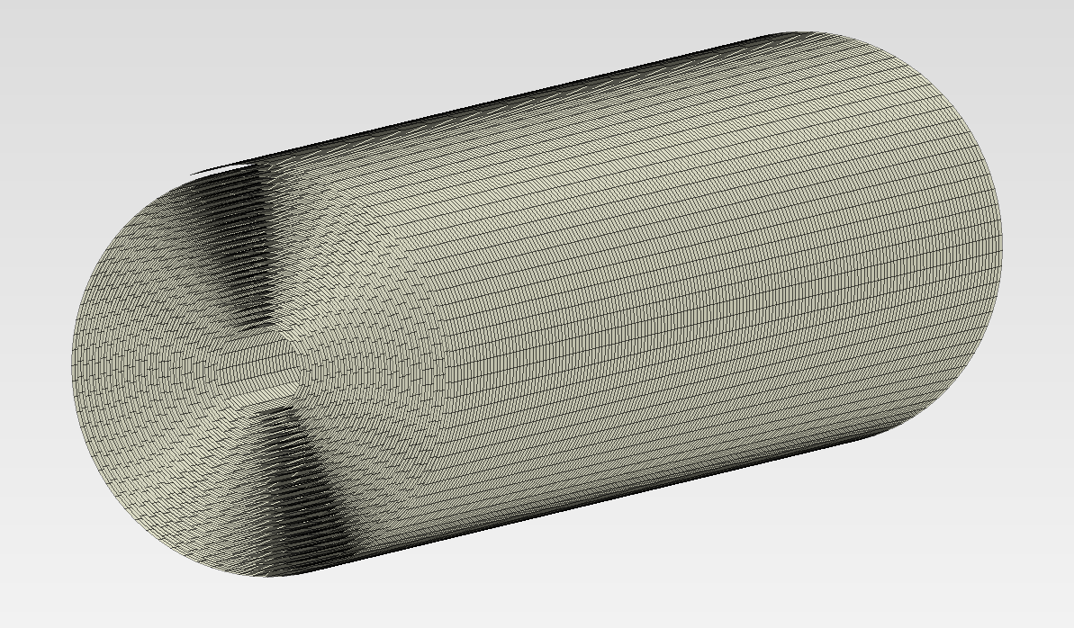
I’m trying to simulate the heating of a spirally wound battery cell (basically ~8 layers of foil wrapped onto itself), and I’m running into issues when trying to mesh the geometry. I tried sweep meshing, but the results don’t look right.
I was thinking about unrolling the geometry and somehow replicating the thermal behavior of the wound version using tie constraints or contacts, but I’m not sure how to best go about this in PrePoMax, or if that is even required/the best idea.
Has anyone here done something similar or has an idea how to approach this? I haven’t worked on this kind of problem before, so any advice or ideas would be much appreciated.
Since you can’t use axisymmetry here, how about shell elements for the thin layers ? This will be much easier to mesh (even if it’s internally expanded to solids anyway). Unless you simplify it further and use e.g. equivalent layers as proposed in some research papers.
Thanks for the suggestion, I’ll definitely look into it. I’ve been considering simplification, but apart from merging the 8-layer stack into some sort of “metamaterial,” I’m not sure how to simplify the model further without losing what I assume are important thermal characteristics.
Is there a way to reduce the mesh resolution along the height of the spiral/cylinder? The maximum element size in the meshing parameters is already quite high, but it seems to have no effect on the final mesh.
Now the only thing that I am left wondering is wether I can set the meshing up in a way so that the inside of the spiral isn’t always much more “choppy” than the windings on the outside. I think this is due to the constant elements per curvature radius setting?
I would assume that the number of elements per degree would ideally become higher when going from outside to inside to keep the “linearization error” (for lack of a better term) constant along the winding model.
I see, so I have to add partitions so that I can select them and use refine mesh to manually increase or decrease the resolution in the selected partition.
I’ll see how far that information takes me, it’s already looking a lot better now.
Thank you for all the help so far!
Or you can try the opposite idea. Use global mesh setting - number of elements per curvature - for the spiral, and then use mesh refinement for other edges to make the elements larger.
Thanks! I’m now quite happy with the level of control I have over the meshing.
One additional thing I’m wondering about: would it make sense to use the Thicken Shell Mesh option for this model? So far, I’ve been modeling each layer in the foil stack as a separate spiral shell. I then apply the appropriate thicknesses via material sections and manually define contact pairs to reconnect the layers using tie constraints, but this feels a bit cumbersome.
However, it seems that using a single spiral shell and leveraging Thicken Shell Mesh to define multiple layers could get me quite close to the behavior I’m aiming for. The problem is: I’m unsure how to assign different material sections or layer thicknesses to the individual layers when using this approach. I found a thread on the forum that seems to ask a similar question: Thicken Shell Mesh, retain layer information, but I am having some trouble with understanding the answer given by @synt.
Can/should Thicken Shell Mesh be used in this context? Or would a different method be more suitable?
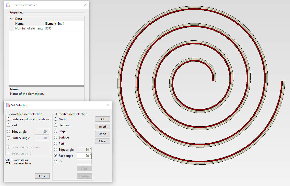
Yes, you can use the Thicken Shell Mesh tool for that. As mentioned in the thread you linked, selecting layers will be a bit tricky but you can do it with the Set selection toolset - try different options, especially those available after clicking “More” (mainly the Face angle option).
I quite like the Composite Shell section idea, have not been able to get it to work though.
I have tried a couple of keyword versions, but the analysis always crashes during the first iteration without any kind of logging except job failed. It also tells me, that the section assignment is missing for all of the elements (despite Element_Set-1 being an element set containing the entire part).
The thermal properties of the materials have been defined and I can use them without issues when defining regular solid or shell sections with them. I am not using the orientation since it appears to be optional and my defined materials only have isotropic thermal parameters right now. The issue may be related to the element set
Sometimes submitting outside of PrePoMax (using standalone CalculiX) may provide more details but CalculiX tends to be pretty vague with its error messages (or lack thereof).
You can ignore this warning or define a dummy material/section to be overwritten by keyword edits.
Be careful with material names containing special characters. Keep in mind that only S6 and S8R elements are supported with composite shell sections.
Thank you for your Input. Sadly I still get the same error after changing the names. The syntax might have been correct already, I must have made a mistake when copying the keyword in the reply. The element type is and has been S8R.
The current keyword version looks like this:
I tried creating an element set and using the name of the element set for the ELSET parameter (which is the correct way to specify it, I think) and I have also tried using the name of the element itself (From_parts-1).
Here is the .pmx (Not 100% sure if this includes the keywords?) Composite_Shell.pmx (1.4 MB)
As usual, it’s probably user error, but I can’t figure out whats wrong…
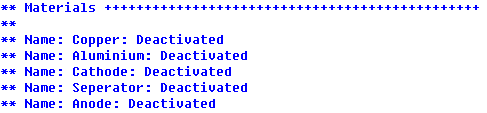
Basically, the problem is that when you submit an analysis (or export input file) with materials not assigned to parts (via sections) in GUI, those materials are treated as deactivated and not written:
So you would have to define them as additional Keyword Edits or assign them via dummy sections in GUI (to be overwritten by custom section keywords defined under the ones created by PrePoMax).
Thank you! Once I assigned dummy sections to for all materials, it immediately worked.
Interestingly, I did not see the additional errors reported (or I am looking at the wrong thing):
Anyway, it seems like it works, and defining the composite structure syntactically in the software is very convenient for me. The only thing that I am missing now is getting the heat transfer between all the partitions, as right now, they do not seem to be linked thermally:
If they were created from separate parts without compounding, they won’t be connected. You can always try to connect such separated regions by merging the nodes or using tie constraints.
There is an open problem and I’m not sure if and how I can solve it when using the Composite Material approach.
The following Screenshot is from the results page, after the composite material has been successfully applied to the spiral shell section and a heating step has been simulated:
The tiny blue arrows indicate where I would need an additional thermal contact (or tie constraints). I don’t really know to to define a tie constraint for these surfaces, as they are only visible after the composite material is used on the shell section, so I can’t seem to access them in the FE Model step where I would define the tie constraints usually.
Without this contact definition, heat can’t flow orthogonally with respect to the spiral winding, which is an issue.
Can this be achieved when only modelling the winding as a shell section and assigning the composite with the keywords?
Those are the expanded shell surfaces but it’s like modeling one shell lying on another. You can still define contact in such cases and it will be “transferred” from midsurfaces to top/bottom surfaces of the expanded shells. If it’s a single part, it would be kind of a self-contact with the same surface as master and slave.
Regarding thermal contact properties, you have to define gap conductance. It can be constant or dependent on contact pressure and temperature. Use a large value if you want to model ideal heat transfer without any resistance.
Of course, an alternative workflow could be to model this with solids using the Thicken Shell Mesh tool (it supports multiple layers too).
Good to know, sadly I have not been able to get the thermal contacts working properly so far.
I think it would be easier and sufficient for me to work with an unrolled model of the winding itself. To get a visual of what kind of behaviour I am looking for:
I think unwinding the foil while keeping the thermal coupling equivalent to the wound connection should be quite doable.
Right now I have the foil stack as separate layers and each of the layers is partitioned by the winding segments. I think if the foil layers are thermally connected as they lay on top of each other (seems to work fine using tie constraints) and then the segments of the foil stack which have thermal contact due to the winding (which obviously are quite far apart in the unrolled model) would also be thermally connected, the general thermal flow characteristics should represent the wound model quite well.
Here is the pmx file which should make it pretty clear what I am trying to do, perhaps anyone could help me with getting the segments that should be in contact due to the winding to be properly thermally connected in the unrolled model: