You are welcome. I finally understood the difference between all the available strains recently.
This is what you have and the origin of your error.
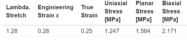
The Strain provided by ccx for Hyperelastic materials is the Lagrangian Strain not the True Strain.
According to your coefficients you should expect a range of true stress values between .84 and 1.49 MPa (I did not compute the volumetric stress) . Your result is 1.01 [MPa] which suggest you are in a pure shear area. That seems correct as the stress is on the high of the crest where one side pulls up and just beside is pulling down.
Hello sir,
Thanks a lot for your answer
Indeed the real material is a I think silicone shore 50 A, and the center is over molded and has a small rigid plastic part at the center (that I neglect and represent as silicone in this simulation)
The result you got is impressive and very close to the real behavior. For the 8 MPA, I was testing different constrains and materials to find out what work best, but the true displacement is around 18 mm.
Could you please share your prepomax and excel files and how you computed C01 and C10 ? it would help me a lot.
Somehow the same run took 10X with PastiX vs. Pardiso on my computer. I’m surprised to see such a big difference between the two solvers in a relatively simple model (no contacts). I did use 1st order hexas for the mesh because I want to perform a mesh perturbation analysis to explore the results. Given the thin walls here, I expect a very sensitive response. rubber_diaphragm.zip (2.0 MB)
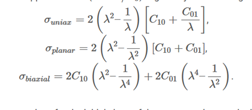
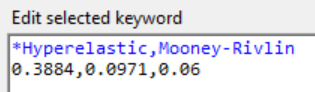
Here again the result with 18mm and 50ShA. For the determination of the C10 and C01 values you can use following formular:
C10 = 0,043 x 1,045^ShA
C01=0,25 x C10
e.g. for 50Sh(A)
C10 = 0,3884
C01 = 0,0971
In any case, there is a simple relationship between Shore hardness and the shear modulus, which makes it easy to derive the Mooney coefficients. I will prepared something next.
But what I noticed is that the real component in the initial position looks different from your data model, right?
But you can calculate another model yourself with the help of the pmx file. wlh70_1_Diaphragm.pmx (5.1 MB)
Can you provide the correct step file or calculated by yourself and measure the deformation force (just an estimate)? Then you can also calculate the reaction force with PPM. This can then give an additional certainty, besides the deformation of the part, whether it all makes sense in relation to the material model.
I would like to throw a question here which is related to this specific problem.
¿Is it safe to model ¼ of a model without knowing a priory which are the buckling patters in the solution?.
I mean, ¿what happens if this membrane has a lower buckling shape/load with a pattern that cannot be built with 1/4th of the model?
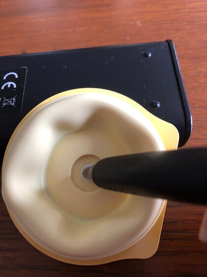
By other hand, when we are punching with the tip of your pencil inserted on the hole, we are applying a BC which constrains displacements in the transverse direction. That is different from a uniform pressure.
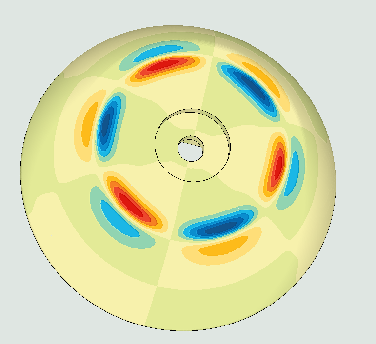
I have found some buckling modes for this shape that are lower than the one induced by the prescribed displacement and that are incompatible with a ¼ symmetry modeling.
If your load is going to be a uniform pressure, I would reconsider the BC.
Short answer, no. The symmetry constraints will impact the deformation and only provide specific buckling patterns.
Then you lose that information from the way the model is built. I’ve seen multiple times in design where we have specific load scenarios with symmetry BCs, and then when you go to the field and see the real part bent in a way that is not modeled, you understand you are losing those deformation modes by the constraints.