I recently completed my participation in the RR3 Tower Finite Element Benchmark (Part 3 – Software Survey), organized by Dr Adam J. Sadowski (Imperial College London) as a continuation of the well-known Round Robin on shell buckling (2022–2023).
This international benchmark investigates the numerical performance of different FE codes for nonlinear shell buckling of an 8 MW wind-turbine support tower under combined axial load, bending, shear, and torsion.
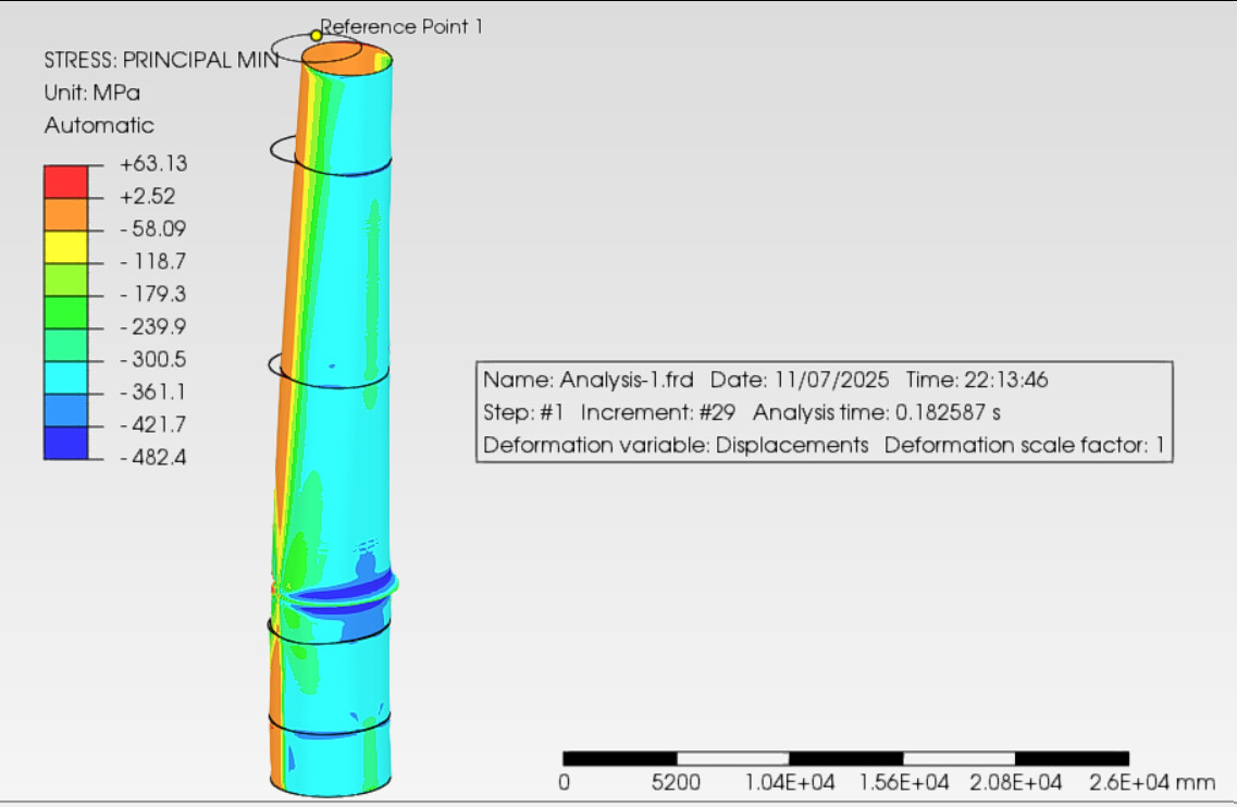
Software setup
GUI: PrePoMax 2.4.0
Solver: CalculiX 2.21 (backend)
Element type: S8 (quadratic Mindlin–Reissner shell)
Model size: ≈ 56 600 elements, 170 000 nodes (≈ 1 million DOF)
Material: S355J0, E = 210 GPa, fy = 345 MPa
Load cases: as defined in the RR3 brief (LC1 without torsion, LC2 with torsion)
What worked well
User experience: PrePoMax offers an exceptionally clear GUI and a very intuitive workflow. Imperfection handling: The “Create imperfection from mode shape” feature is much easier and more transparent than the comparable process in Abaqus/CAE. Linear static (LSA) and Linear buckling (LBA) analyses ran flawlessly.
The first 50 eigenmodes matched well with Abaqus reference results (differences < 10 %).
Where the solver struggled
Material nonlinearity (MNA):
Converged only up to ~25 % of total applied loads (LPF ≈ 0.25).
Even after testing all solver options (Spooles, PaStiX, Pardiso) and fine-tuning increments, the run aborted beyond that point.
Geometric + material nonlinearity (GMNA / GMNIA):
Failed to converge for combined load cases (axial + bending + shear + torsion).
The CalculiX solver currently seems to tolerate one load component at a time, but not several simultaneous loads and rigid-body couplings.
Single-load tests, however, did complete successfully.
Summary
Analysis type
Status
Remarks
LSA
stable, consistent
LBA
matches Abaqus reference
MNA
convergence up to ≈ 0.25 LPF
GMNA
non-convergent for combined loads
GMNIA
non-convergent for combined loads
Overall impression
PrePoMax / CalculiX is excellent for linear and imperfection-based analyses and provides a very smooth user experience.
However, nonlinear path-tracing with multiple simultaneous load components remains beyond the current solver robustness.
Still, for education, research, and preliminary design, it’s an outstanding open-source alternative.
Many thanks to the PrePoMax developers for GUI usability.
Which version of Abaqus/CAE was used ? Since Abaqus 2024, imperfections are supported directly in the GUI and don’t require keyword edits.
CalculiX has a known issue with shells + rigid body constraints + Nlgeom leading to non-convergence. In such cases, it might be better to use solid elements instead. PrePoMax has the Thicken Shell Mesh tool facilitating this conversion.
Also, Abaqus has a powerful Riks (arc-length) solver which is often requested by CalculiX users but still unavailable.
I also tried the analysis with solid elements (C3D20R), using both Spooles and PaStiX solvers, and tested various increment sizes and load-scaling strategies.
The results were essentially the same as with shell elements (S8) – the solver still failed to converge once multiple load components (axial + bending + shear + torsion) were applied simultaneously.
It seems the current CalculiX implementation can handle single-load nonlinear cases reliably, but combined-load steps with rigid couplings remain problematic.
I have worked with such combined load steps in the past without issue for large models under non linear procedures. Maybe a specific limitation or modeling approach that triggered the non-convergence?
Can you share the data you have used for such benchmark? Maybe the people here in the forum can help to achieve better results
I would love to share the inp files for PrePomax but they are all pretty large (25MB>), cant even upload to Github. If you have a good platform for exchange I will upload all I have.
You could use any hosting website, possibly persistent (but requiring account from your side) unlike WeTransfer so maybe OneDrive, Google Drive or Dropbox.
However, it would be better to share the .pmx file (.inp can’t be remeshed) or at least the geometry in .step format.
it will be expanded to C3D20 internally, this element type and single layer only can cause a problem in convergences during plasticity of materials and large deformation analysis. It suggested using S8R element with composite options, at least four layers to multiplied number of integration points through the thickness to capture better.
Submitting the input deck from this file in Abaqus also leads to non-convergence at 0.124. Does this mesh contain imperfections or is it the ideal geometry ?
Did you use any kind of stabilization or artificial damping to aid convergence in Abaqus ? I wonder how this model differs from the one you successfully used in Abaqus (e.g. what Abaqus features are missing here). Apart from the mesh, I assume.
Just realised your result is correct, if your ABAQUS analysis aborts at about 0.124 this corresponds to a LPF (Load Proportionality Factor) of 1.24 which is about the same as from my analysis (1.2). So everything good with your analysis. (i applied the load times 10)
If you get the same result in PrePoMax then it would be nice.
Oh, I have miss this one. I’ve been busy these days.
Hi Hnrwagner, are you Mr.Wagner from Braunschweig?. In that case It’s a pleasure to have you in the forum.
The recommendations in forums usually indicate that the best way for getting response from others is to ask the question precisely. I think the best way is to say that something isn’t working. Nothing beats a good challenge.
Is it one element through the thickness ? Which type ? And tie constraint is used for the top layer (I see its nodes aren’t coincident with the bottom part) ?
Perhaps I should challenge the guys from the FreeCAD forum. One of them developed own solvers dedicated to problems of this kind (including silos: Calculating a silo structure) and circumventing the significant limitations of CalculiX in this regard.
Also, it would be interesting to use a mesh with imperfections.
This is actually just a visual effect: the nodes are coincident. Look at the front side, you will see that the upper flange has been extruded inward. The element used is S8R, one layer.
I will complete the full analysis if I find the time.
For some reason, I cannot open files from other users. There is always a warning regarding corruption or incompatible version. Could you share your amplitude definitions?. By other hand, we recently found a case (Colliding tubes) in which the convergence was failing due to the set up in the support, far away from where every body was searching the issue.
@FEAnalyst – in a previous post I reported a similar issue with one of your files. You changed something, resent the file, and suddenly I was able to open it. Do you recall what modification you applied?
 Software setup