I need an idea how to mount a rubber ring on a shaft, so that the inner diameter of the rubber ring has contact with the shaft. The ring has a preload when installed which I would like to see. The model is very simplified. Does this work at all with PPM v1.4.1?
Which steps are necessary?
You could utilize symmetry here (maybe even axial), no need to model the whole 3D parts.
If you want to simulate mounting, you should do it in such a way that represents the real-life process. If the ring is simply stretched and pulled on the shaft, you should stretch and pull it in the simulation as well (using two steps). Symmetry will help you with boundary conditions. Also, use displacement control instead of force control whenever possible (to reduce the risk of convergence issues).
If the aim of the analysis is the rubber seal, you could model the seal in its initial unloaded dimentions, and the shaft with it groove in a reduced diameter, so the seal doesn´t touch it. Then, apply a radial deformation to the shaft in order to put in real dimention (don´t know if is supported by Prepomax by the moment, you need to define a circular coordinate system related to the nodes of the shaft, and then the first DOF will be the radial displacement) , so the oring will be stretched as in real life, and you avoid the real mounting operation that normally is not the aim of the analysis.
You could do a second load step were you decrease the diameter of the cilinder to get the oring in its final dimention with the streeching and compresion from outside.
And a third step with the working pressure applied in the seal to see if it extruded trough the clearance between shaft/cylinder. The first two steps i have made in the past, but I´m not sure of CCX will be able to simulate accurately the oring extrusion, the mesh must be very very fine in that area.
I did’t try this in calculix but in other FEA codes you can simply have an initial overclosure, which is resolved in the contact iterations. I used this in the Inventor stress analysis for bolt pre-tension. The bolt was slightly shorter than the thickness of the plates it had to clamp.
Yet be sure that you don’t resolve the overclosure by mesh modification prior to the analysis. That would lead to a stress-free part.
You could also try thermal expansion with cool down, which is also a way to simulate bolt pre-tension. if you are limited to single step analysis.
That’s the easiest way to do this type of problems…
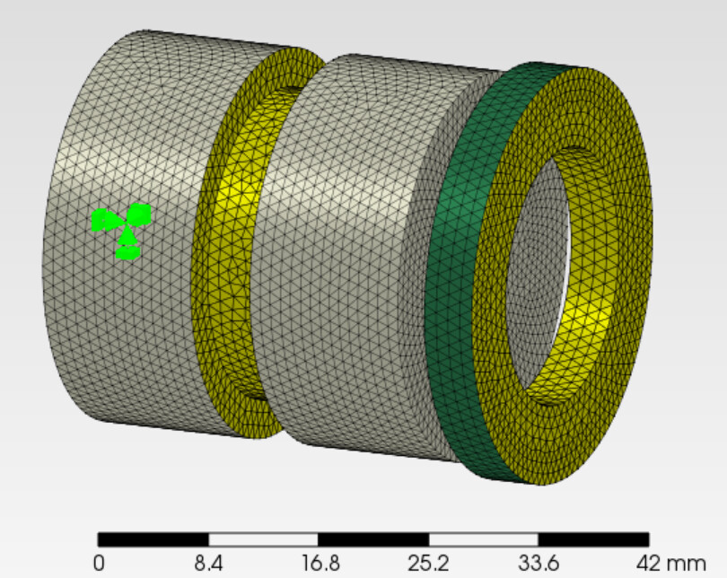
See the attached model file (PrePoMax v 1.4.1) - @wlh70 I kind of cheated by moving both surfaces, the shaft and the ring, but I think you can play around it and see what makes sense for your simulation needs. In general, I would follow @SergioP1975 approach, since we don’t care much about the real mounting operation of the ring. assy_shaft_ring_a.pmx (1.0 MB)
I don’t know if it can resolve such large interference values, ~ 2.0 mm seems much more than what we typically see in other applications where the interference fit works like a charm- but I could be wrong.
I made a model of a chain and the pin is connected to the outer link with a press fit (modeled in the geometry offset as measured). So this contact pair moves together and that is assumed as normal steel to steel frictional contact with µ = 0.1.
That should work with rubber in a similar way. Please check the contact penetration (COPEN) and modify the contact stiffness if needed. https://fatigue.pro/2023/07/a-chain-is-only-as-strong-as-its-weakest-link
First of all, thanks to all the advice here in the thread. I have followed them all carefully and I am now trying to get it right myself. I know the method of expanding the shaft from my former colleagues in the FEA department, who have also done this with Marc Mentat.
The real difference between a calculation between 3D axisymmetric or 2D axisymmetric I still have to work out, but that is another topic.
Marc is powerful in this type of analysis conditions, especially with the contacts; they work so well! You can also analyze 2D axisymmetric and import the state of stress to a full 3D model using the pre state keyword.
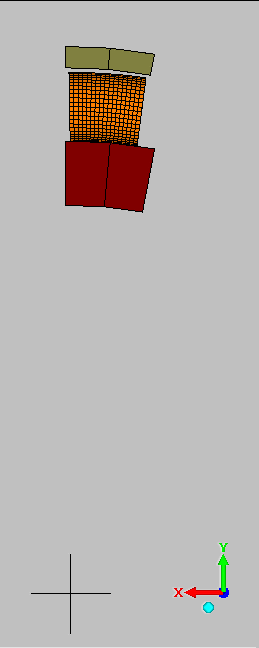
The good thing is that calculix is, by default, a 3D axisymmetric model. Even though you see planar elements in my model, these get expanded 2 degrees with appropriate boundary conditions – see: 6.2.30 Eight-node axisymmetric element (CAX8 and CAX8R) from the ccx manual. So, no need to worry much about the difference between the 2D representation and the actual 3D model in ccx. Give it a try to the model I uploaded to see if the stress/strain/disp values are close enough to what you would expect.
If you want to simulate the extra stretching due to assembly I would add an extra step, but with the oring always in the same position, it doesen´t have sense to model the sliping along the shaft, will not give you any usefull data and will increase a lot the time to solve and dificulties:
With the oring modeled in the initial shape (and final position, in the groove), shaft (only the groove area) with artificial reduced diameter, and cilinder with artificial increased diameter:
step1 => Increase the diameter of the shaft/groove to the real size of the shaft (the groove must finish with the shaft diameter, to check if during assembly the rubber will stretch too much
step2 => Reduce the diameter of the shaft/grove to the real size of the grove (the oring gets in the stretched dimention)
step3 => Decrease the diameter of the cilinder to the real dimention, then the oring gets the final state, stretched and compressed
step4 => Apply pressure to the oring exposed faces
In this case I have not applied *transform but it should work.
I have used the polar equivalent (x,y) for r and (-y,x) for theta to avoid rigid body rotation.