Dear All,
Can you please share an example of how to build the model of the double-bearing overhung rotor
Dear All,
Can you please share an example of how to build the model of the double-bearing overhung rotor
Could you share your file using a different hosting website ? This one requires registration. You could use e.g. WeTransfer or Google Drive instead.
Please share ur email id
I just sent you a private message regarding this.
To apply bearing supports, you should go back to your CAD software and make proper face or volume partitions like this:
Then after exporting back to step you will be able to use those faces for bearing supports.
I use FreeCAD and such partitioning is not very convenient there (quite a lot of manual work), but other CAD software may handle it with ease.
sure i will modify my rotor but how to develop the model please.
So that we can calculate the forces acting on the bearings and rotor deformation. we want to spin the rotor at 10,000 rpm . And the max torque generated by motor rotor would be 25Nm.
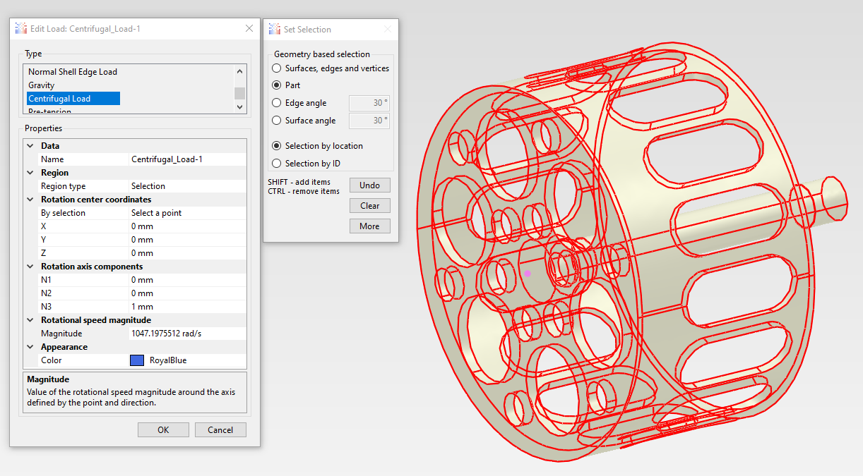
You will definitely need a static step with centrifugal load where you can specify rotational speed in rad/s (or enter it in RPM and PrePoMax will do the conversion):
 - Tutorial 6 - Rotating disc")
Of course, proper boundary conditions / constraints will be needed for bearing supports. Details depend on how you want the shaft to be supported. There are different techniques involving springs (if you know bearing stiffness in each direction), kinematic coupling or rigid body constraints and optionally boundary conditions in a local cylindrical coordinate system.
Finally, you can follow the static step with frequency and complex frequency steps if you want to perform modal analysis as well.
Sure Iam checking the same video. Can u help me understand how to measure the forces at bearing support points
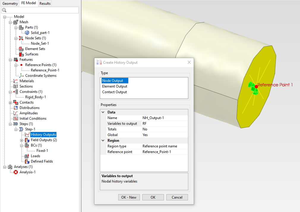
It depends on how you define the supports but assuming that you use rigid body constraints (or even kinematic coupling constraints via keywords) for that (since that’s a common approach), you just have to request history output of RF for reference points of those rigid body constraints:
You will then obtain the reaction force output in the Results tab, but only if you define boundary conditions for these reference points.
So, to sum up:
Thanks a bunch further we will be using the below link from SKF to choose the bearings and co relate the results
Please check if the model is correct . This is to measure various parameters with RPM 10000.
Torque applied 25Nm and BC fixed at first bearing close to overhung rotor
You should consider two aspects:
The idea is we want to check the worst case scenario.
As we have 2 bearings we are trying to get the force acting at each bearing location based on maximum torque and max RPM.
Based on this information we are planning to choose the bearing using SKF tool.
Do you think this is a good approach?.
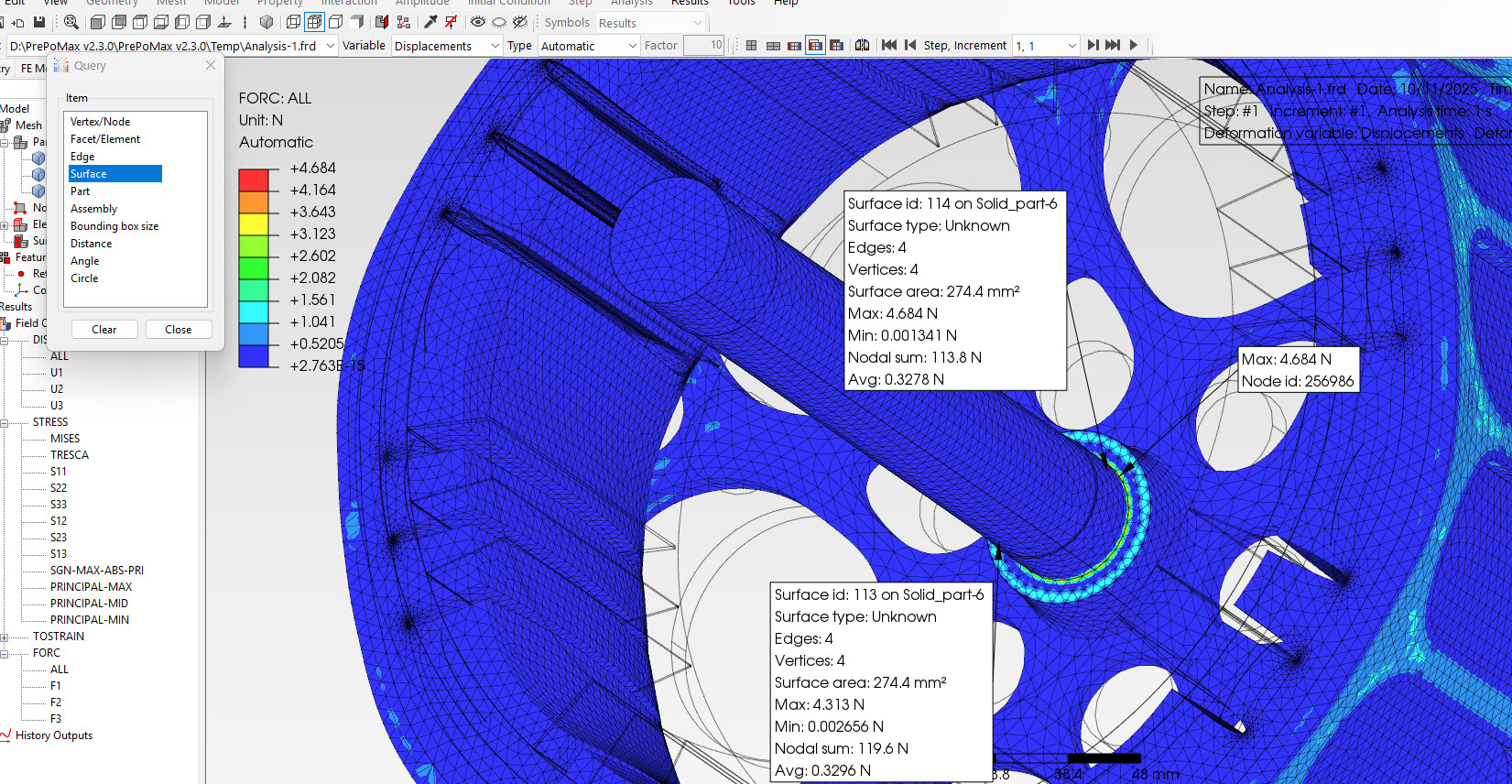
Analyzing the worst-case scenario is indeed typically a good idea. Finding forces in the connection or support regions modeled in a simplified way (such as using 1D elements) is also useful as long as said supports are defined realistically - proper BCs in both bearing locations in this case.