Hi,
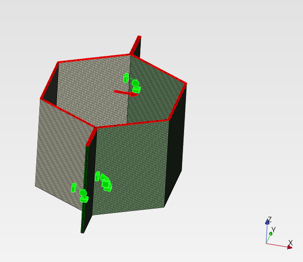
I am trying to work out the shear modulus of a honeycomb core. For this, I have made a simple model of a hexagonal unit cell. My idea was to apply fixed boundary conditions to one side of the cell and surface traction with a horizontal force on the other. This should then simulate a shear load as expected when being used in a sandwich panel (ignoring bending contributions).
From the displacement dx I would then work out the homogenised shear modulus G13 (or G23) using the area of a bounding box of the entire unit cell in the xy plane (including empty spaces) : Shear modulus - Wikipedia.
As the honeycomb structure would be a periodic (infinite) network, how would I go ahead and set the symmetry boundary conditions in x and y?
The honeycomb cell in this example is a standard expanded aluminium core like this one:
Cell size: 6.4 mm (1/4")
Wall thickness 0.07 mm
Core height, l: 5 mm
Foil material: Aluminium foil 3003, modulus ~ 70 GPa
I have tried to use “typical” symmetry boundary conditions on all vertical faces in contact with a neighbouring cell but this does not appear to be the correct approach here:
I have also tried to add Node sets to opposing faces and then add a Calculix keyword such as:
U_right - U_left = 0
but also with no luck…
Would this be the way forward linking each individual node on opposite faces?: *EQUATION
…and if so, would GMSH ensure somehow the nodes being perfectly symmetric on each face?
Here is the example pmx file, created in PrePoMax v 2.3.3.dev:
I would much appreciate any hint on how to set such model up correctly. Thank you all the same if you wouldn’t know either.
which looks correct… need to have a good look at the details still but at least the displacement contours are as expected…
For anyone else trying to use the code linked above, here is a step by step guide when using this in PrePoMax (v2.3.3.dev):
Mesh your parts, ensure symmetry on opposite faces.
Create Node Sets of the opposing faces. These have to be called Face_X0, Face_X1 and Face_Y0, Face_Y1 and Face_Z0, Face_Z1 for the x, y and z symmetries. Use the ones needed only.
Export the file as a Calculix .inp file. Make sure it is only the mesh and not already set bc or other things as the code crashes.
Run the Python script through bash python periodic.py your_model.inp
You should get a periodic.eqo file in the same folder as your .inp file, copy the data into the Calculix keyword editor under new constraint.
Add any other constraints and Steps as needed → Run file.
This worked for me…
The GitHub file required the first face to be at 0,0,0. I have updated the code so that this is no longer needed; in my case 0,0,0 was at the centre of the honeycomb cell which the code didn’t like:
I have not tested this extensively yet, so use it with caution, report back if it works or if it doesn’t…
The updated honeycomb core file is here is case of interest to anyone:
Thank you very much for the Script and instructions.!!!
I see something unnexpected in your displacement field and I would like if you or any other one could help me to clear my doubt.
It’s not 100% confirmed but seems ccx uses a Stress Sign convention as descrived in the picture.
Commonly, first index of Shear Stress/ Force, refers to the plane where the force acts and second is the direction.
I would expect forces in Plane 1 and 2 and both pointing in direction 3. Now seems you are apling Force in plane 3 direction 1. ¿Wouldn’t that lead to G31 value?
¿Does You Shear Modulus agree with Catalog Values?
For the 1/4 honeycomb core example (83.3 kg/m3) above, considering the two load cases in principal directions I am getting a displacements of:
dx = 0.00265 mm for F1 = 10 N or
dy = 0.001825 mm for F2 = 10 N
With the bounding box area, A = 6.54 mm x 11.0851 mm and core height of 5 mm these are the derived bulk shear moduli:
G13 = 260 MPa and
G23 = 378 MPa
I would think this is in fairly good agreement. The differences in values will likely be caused by the differences in geometries tested here and used in the experiments. The values given in the datasheet are on expanded honeycombs. These may have been over or under expanded (slightly) and the cell corners in practice will always be rounded and not as sharp as in this example etc. So, I’m happy with the results.
Happy to hear any thoughts on this (or see other examples)…
I would always assume:
G12 = G21
G13 = G31
G23 = G32
as the material is orthotropic; but again, happy to be taught wrong.
[kennethfugate] Mecway’s user (kennethfugate — Forum) made some years ago a nice comparison in between a full modeled honeycomb panel and compare it to the solid Orthotropic equivalent.
Difference in between both in terms of maximum deflection under bending ended below 5%.
I recommend you take a look at his approach and related documentation.
"In general terms, the shear forces normal to the panel will be
carried by the honeycomb core. Bending moments and in-
plane forces on the panel will be carried as membrane forces
in the facing skins.
Before analyzing a large structure, the modelling technique should be checked by modelling a simple panel with known results."
There are many papers convering the determination of effective elastic properties of hexagonal honeycombs since they are very common structures. They often cite the classic book “Cellular Solids: Structure and Properties” by Gibson and Ashby where analytical approach is presented.
Those two particularly caught my attention:
There are also some interesting papers from NASA but they seem to be inaccessible at the moment.
Thank you both for the literature data. I’ll have look…
But there appears to be a more basic issue when applying periodic boundary conditions, which is the need of a mesh to be perfectly symmetrical. How can this be achieved (without failure)?
Below an example of a honeycomb cell with thicker walls to better visualise what is going on. The model is prepared in FreeCad as an extrusion to create a corrugated shape (half hexagon). This is then mirrored along a datum plane. Double checked and the shapes should be perfectly symmetric. The shape is then exported as shells and meshed as Shell_gmsh. Used the thicken shell option here to visualise the mismatch in the next step:
Unfortunately, such mismatch prevents periodic boundary conditions to be set. Any suggestions how would this need to be tackled? … or better, how can a perfectly periodic mesh (node positions) be ensured on the desired faces?
Sounds like a reasonable plan, but afraid to ask: how to create a copy of a part?
I can delete a meshed part or transform an existing but couldn’t find an option to copy :s
Also, the mesh of the initial part will need to be perfectly symmetric to allow rotation and translation. Mirroring may be a better option in such cases as this would be the only way to ensure nodes will always align?!
There’s no separate Copy option. When you choose Translate or (in this case) Rotate, you can change the operation to Copy and translate or Copy and rotate, respectively. Unfortunately, there’s no mirroring. You would have to do it outside of PrePoMax, e.g. in Gmsh.
@Matej, this may be a nice new feature to be added As mentioned, if one likes to create periodic boundary conditions, exact opposite node positions are a must.