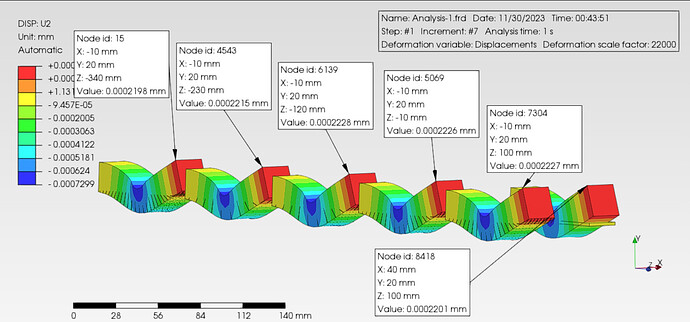
This should not happen. I will look into it.
The reason that there are no gap elements in some cases is that now the gap stiffness is computed by distributing the assigned stiffness to the nodes. This is done by evaluating the nodal weights which are used to scale the stiffness in order to achieve a constant stress distribution if the load is uniform. And in some cases, the nodal weight is 0. In this case, the gap elements (the same goes for the surface spring) would have a stiffness of 0 which is not supported by CalculiX. So, no gap element (or spring element) is created.
What happens if the load is not uniform is hard to determine.
Of course, I will make sure to include it in the documentation for the upcoming stable release.
In this case, the deformations of model 1+2 are significantly different from those of 3-5. Model 2 is only rotated 90° to model 3 (this also generates GAP elements at the corner nodes in model 2). So using compression-only constraint on square 2nd order faces, by using not uniform loads, should at least be treated with caution…
Have you noticed that displacements are reduced close to 1/2 in the example above. That means Stifness is twice or the number of springs is x2. I would say 1 and 2 are right and there is some stiffness missing in 3,4 and 5 when distributed along the triangles. ![]()

Are you using NLGEOM = ON or OFF?
For all my examples NLGEOM = ON
Later i will test model 1 with contact for comparison.
probably it’s worth to try in comparison with linear element type also.
*edited
below example results of linear and quadratic hexahedral element, it seems the discrepancy are due to mesh and element formulation not by nodal spring distributions. However, a further contact analysis is required to give more insight.
I think the problem is nodal spring distributions in triangular faces.
but my result shown consistent, it’s related to mesh and element formulation. Linear wedge element shown more stiff and quadratic wedge given similar to previous models.
below result of linear hexahedral and incompatible ones, fully integrated element shown similar to linear wedge.
I am using the same nodal weights that are shown in the image. One can check this if an example with one finite element is prepared. Then, a stiffness defined using the user interface can be easily checked in the .inp CalculiX file in the spring keyword definition.
Here for comparison model 1 with contact. It is noticeable that the coarse tet model is the closest to the contact model:
pmx file (v1.5.5)
ct.pmx (319.6 KB)
1st and 2nd order comparison:
below simple test compared to contact analysis for linear and quadratic hexahedral element. It has shown more stiff, probably due to simplification of compression-only models
Here it is especially important not to over constrain (I have removed that X plane. Poisson is trying to expand laterally) and be careful not to over-dimension the Surface stiffness ( 4200000-42000000 N/mm ) as it can lock some of the elements. Last small differences come from the different elements.
By other hand we are comparing very small numbers compared with the model dimensions. I would say they are very good results.

i still try to understand the problem since i can not reproduce, below my result using the same mesh.
Thank you. Here are my new results, all i changed against my previous model is the reduced compression only stiffness to 42000000 N/mm (i would be supriesed if the model is over constraint by keeping the x direction fixed. It acts like a symmetry BC).
Now all models show similar displacements except of course the stiffer contact model. But the results show what i mentioned earlier:
…compared with hard contact:
I agree. Thanks for your file. It has provide some more light on the usage of Compression Only and how to get the best from it.
I think starting with low value is a good strategy and later increase to see where one can arrive. Also take advantage of the second round to eliminate some areas in pure tension.
Regarding overconstraining it is probably no the right word. I don’t mean it is wong constrained , I’m refering to the fact that we are comparing performance. Only compression Overclousure function depends on the spring elongation “d” not only u2. That means any lateral displacement will induce reaction forces too. d=sqrt(dU1^2+dU2^2+dU3^2). That is not the case in the contact if there is no friction.
Look the corners.
well, i did not find this problem on my simple test case, but thanks for mentions.
however, when this had relation with mesh refinement it’s a normal of finite element method.
Hi Synt,
Maybe you could comment or provide some hint about how you set up your model to improve and get such a uniform solution and everybody can learn and benefit from your experience at the same time the trust in Prepomax increases.
If not , the picture is no more no less than a picture.


