# Body Interaction - I created a mess
**URL:** https://prepomax.discourse.group/t/body-interaction-i-created-a-mess/3013
**Category:** General Questions
**Created:** [October 14, 2025, 4:19am UTC](https://prepomax.discourse.group/t/body-interaction-i-created-a-mess/3013 "2025-10-14T04:19:42Z")
**Posts on this page:** 6
**Page:** 1
### Author:  [@JKnight](https://prepomax.discourse.group/u/JKnight)
#### Post date: [October 14, 2025, 4:19am UTC](https://prepomax.discourse.group/t/body-interaction-i-created-a-mess/3013/1 "2025-10-14T04:19:42Z")
I’m testing several design ideas to see how much relative strength they add. I’ve got someone involved who wants the test to run a certain way, so I need to show both bodies interacting so they understand.
I exported STEP files from Solidworks with the parts tangent to each other. Both are the same material. I created a surface interaction and 3 contact pairs because the bodies touch in 3 places, even though there are only 2 bodies. **Is that overkill?**
One body has a Displacement\_Rotation BC where all DoF are set to Zero.
On a far surface of the second body, I selected a surface that rotates two an amplitude: 0.175Rad (10 deg). I’d like to increase this to 30 or 40 degrees, but I figure I should get it working first.
This motion should drive the two parts into each other until they bind up and cause the main body to flex.
The Analysis took 2.5 hours and failed with results. It appears the larger body is moving upward? I’ve messed up something fundamental, but I’m not seeing it. Maybe it will be clearer in the morning.
These parts are both symmetric, so I’d also like to cut down on computation by slicing it in half, but one thing at a time.
> **[Tower and Bridge.pmx](https://drive.google.com/file/d/1u4euBuNjKE81p__ljsft3-verIAqw_zI/view?usp=sharing)**
>
> Google Drive file.
---
### Author:  [@FEAnalyst](https://prepomax.discourse.group/u/FEAnalyst)
#### Post date: [October 14, 2025, 7:03am UTC](https://prepomax.discourse.group/t/body-interaction-i-created-a-mess/3013/2 "2025-10-14T07:03:02Z")
> [@JKnight](#):
>
> I created a surface interaction and 3 contact pairs because the bodies touch in 3 places, even though there are only 2 bodies. **Is that overkill?**
Contact definition should cover all surface pairs that may come into contact during the analysis. But in this case, it could be one pair with multiple faces on each side.
> [@JKnight](#):
>
> On a far surface of the second body, I selected a surface that rotates two an amplitude: 0.175Rad (10 deg).
You shouldn’t apply rotational boundary conditions directly to faces of solid parts since the nodes of solid elements don’t have rotational DOFs. You can use a rigid body constraint to prescribe the rotation: [https://www.youtube.com/watch?v=2upPxL45OZg](https://www.youtube.com/watch?v=2upPxL45OZg)
Also, if possible, avoid applying boundary conditions to faces involved in contact. This may cause an overconstraint.
---
### Author:  [@JKnight](https://prepomax.discourse.group/u/JKnight)
#### Post date: [October 15, 2025, 4:53pm UTC](https://prepomax.discourse.group/t/body-interaction-i-created-a-mess/3013/3 "2025-10-15T16:53:28Z")
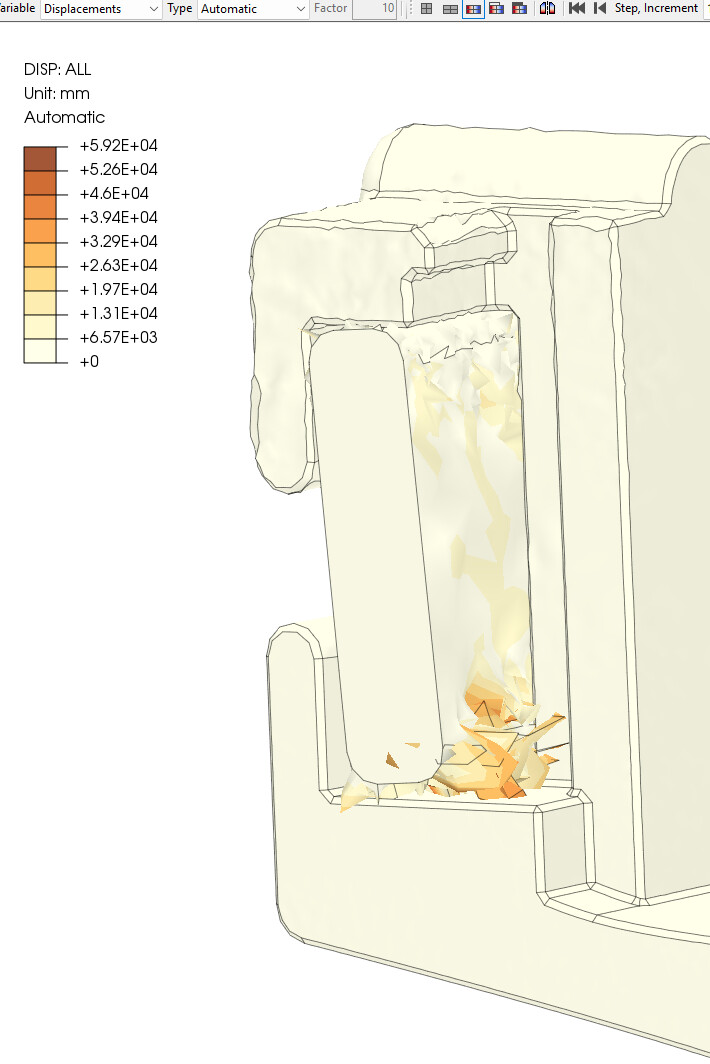
Hmm… I’ve changed most things, and I’ve still got ridiculous results. The material itself seems to be exploding it to large jagged crystals.
Both bodies are the same material - non-linear plastic. Green surfaces are fixed (front and back).
Yellow is contact surfaces, all the way around
Red is a Rigid-body constraint to a Reference Point with a smallish displacement. I hope to see the stress in the C-shaped head near the contact area (and some in the “diving board” leading there)


> **[Tower and Bridge.pmx](https://drive.google.com/file/d/1Ea4eu9ZnMaOYtKSU0h_bkvzOd1AFylGo/view?usp=sharing)**
>
> Google Drive file.
I’ve tried to shorten the compute time by limiting the number of sub-steps and leaving the mesh relatively course. Once I have a setup that seems to work, I may dial those a bit finer to improve results and let it run for a few hours.
---
### Author:  [@FEAnalyst](https://prepomax.discourse.group/u/FEAnalyst)
#### Post date: [October 15, 2025, 5:10pm UTC](https://prepomax.discourse.group/t/body-interaction-i-created-a-mess/3013/4 "2025-10-15T17:10:43Z")
Those are the artifacts from a failed increment; it often looks like this right before the analysis fails to converge. Watch out for rigid body motions - you may want to fix that one unconstrained rotational DOF as well.
Also, the last point of your plasticity definition seems to have a superfluous zero in the plastic strain:

---
### Author:  [@JKnight](https://prepomax.discourse.group/u/JKnight)
#### Post date: [October 15, 2025, 5:13pm UTC](https://prepomax.discourse.group/t/body-interaction-i-created-a-mess/3013/5 "2025-10-15T17:13:34Z")
Thank you for the quick response, you help is part of what makes this product and amazing learning tool (and an amazing tool in general). I’ll fix the plastic strain.
When you say I should watch out for rigid body motions, does that mean I might be better off applying a force to that reference point?
Failed increment - should I work with smaller steps (greater in number)?
---
### Author:  [@FEAnalyst](https://prepomax.discourse.group/u/FEAnalyst)
#### Post date: [October 15, 2025, 5:23pm UTC](https://prepomax.discourse.group/t/body-interaction-i-created-a-mess/3013/6 "2025-10-15T17:23:29Z")
> [@JKnight](#):
>
> When you say I should watch out for rigid body motions, does that mean I might be better off applying a force to that reference point?
What I mean is that in a static analysis, you should make sure nothing can move freely so you have to apply BCs with proper DOFs constrained/enforced to all parts or rely on contact to prevent free movement of some parts but this often fails and causes nonconvergence before contact is fully established.
Normally, you can only use translational DOFs with solid parts, but here you added a rigid body constraint whose reference point also has rotational DOFs that should be fixed as well.
> [@JKnight](#):
>
> Failed increment - should I work with smaller steps (greater in number)?
Some good practices are to:
- break the analysis into multiple steps if possible (here you could move the upwards and sideways in two subsequent steps if it doesn’t have to happen at the same time)
- specify the initial increment size of 0.1 or 0.01 s
- use low enough minimum increment size (e.g. 1e-6 s) - yours seems to high
- increase the maximum number of increments (even to very large numbers such as 10000, it won’t do any harm) - yours is very low here and the analysis may get interrupted just because it runs out of increments